Honeycomb structure

a honeycomb and structure technology, applied in the field of honeycomb structure, can solve the problems of difficult uniform loading of catalyst onto the surface of the partition wall, difficult effective use of catalyst loaded on the root portion, and ineffective use of catalyst, etc., to achieve effective use, and increase the geometric surface area

Active Publication Date:
View PDF4 Cites 4 Cited by
  • Summary
  • Abstract
  • Description
  • Claims
  • Application Information

AI Technical Summary

Benefits of technology

[0021]A honeycomb structure of the present invention has projecting portions arranged to project into cells, and hence, a geometric surface area of partition walls can be increased by the projecting portions. In particular, a tip curvature radius R of an apex of each projecting portion is from 0.01 to 0.1 mm, and hence, a catalyst is also effectively loaded onto tips of the apexes of the projecting portions. Furthermore, side surfaces of the projecting portions are inclined to the surfaces of the partition walls at an inclination angle of 40 to 70°, and hence, catalyst accumulation is hard to occur in roots of the projecting portions. Consequently, in the honeycomb structure of the present invention, the catalyst can uniformly be loaded onto the surfaces of the partition walls including the tips of the apexes of the projecting portions. Therefore, in the present invention, the catalyst loaded onto the honeycomb structure of the present invention is effectively used. Furthermore, in the honeycomb structure of the present invention, a height H of the projecting portion and a hydraulic diameter A of the cell satisfy a relation of 0.04≤H / A≤0.4. Therefore, the geometric surface area can effectively be increased, and rise of pressure loss is inhibited.

Problems solved by technology

However, when this honeycomb structure is used as a catalyst carrier, there is the problem that a catalyst is not effectively used.
In this way, it is not easy to uniformly load the catalyst onto the surfaces of the partition walls including the fins in this manner.
Consequently, in the honeycomb structure of Patent Document 1, the catalyst loaded onto the root portions is especially hard to be effectively used, and improvement of a purification performance is hard to be expected from the amount of the catalyst to be loaded.
On the other hand, when a large amount of the catalyst is loaded to achieve the improvement of the purification performance, through channels for an exhaust gas narrow as much as the amount of the catalyst, and there is also the problem that pressure loss after the catalyst is loaded rises.

Method used


Image

  • Honeycomb structure
  • Honeycomb structure
  • Honeycomb structure

Examples


example 1

[0072]In Example 1, a forming raw material to prepare a honeycomb structure was initially prepared. Specifically, a binder, a surfactant, a pore former and water were added to a ceramic raw material to obtain a forming raw material. Additionally, as the ceramic raw material, cordierite forming raw materials such as kaolin, talc and alumina were used.

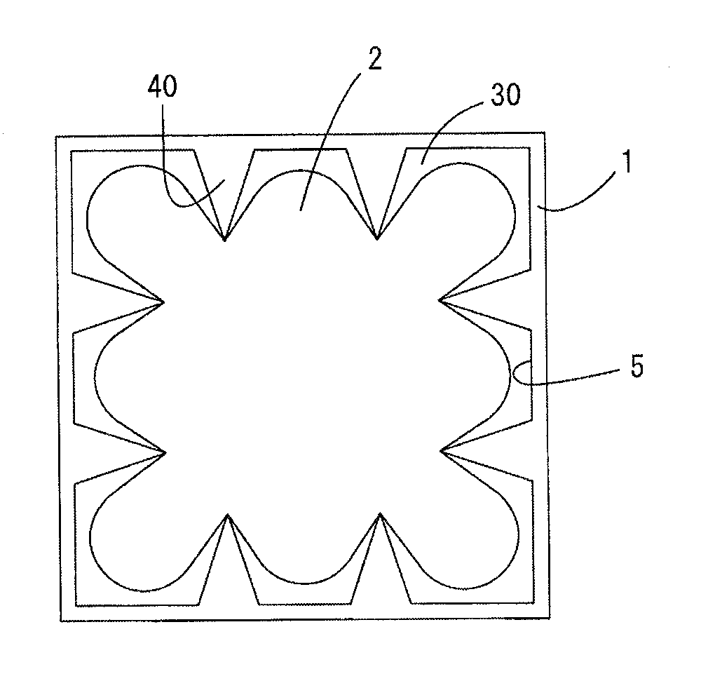
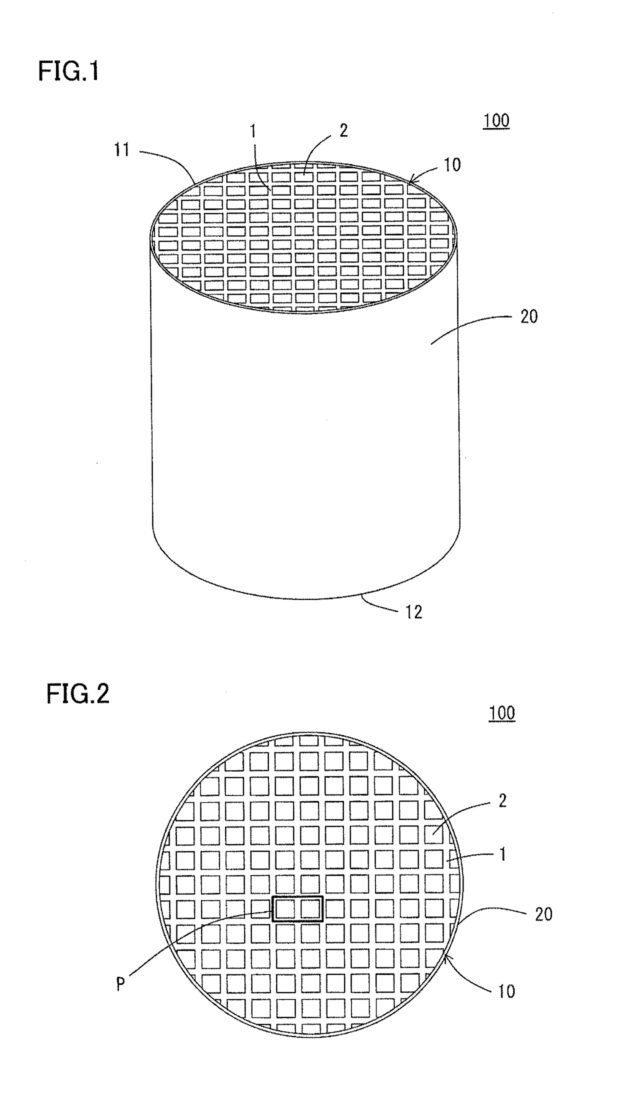
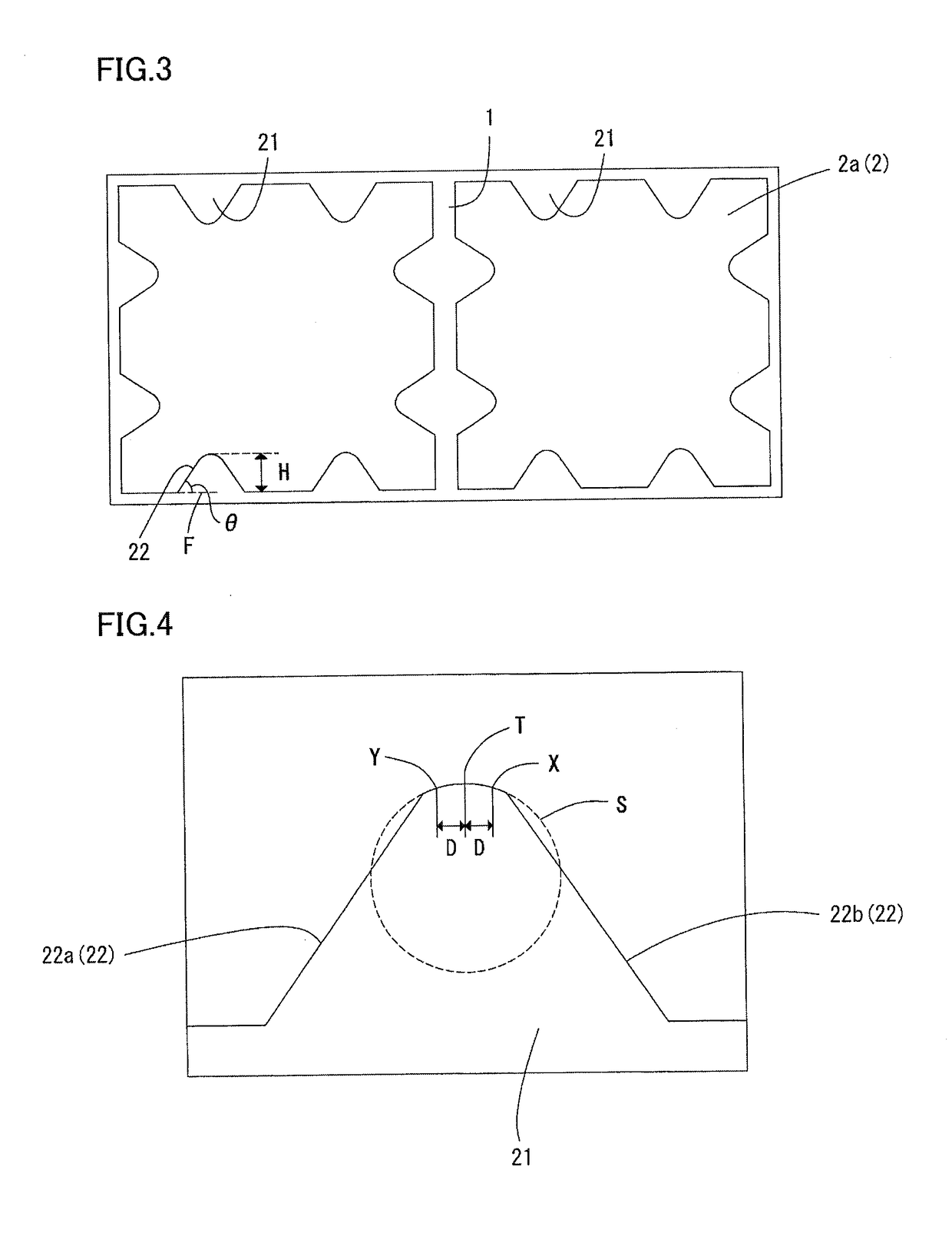
[0073]Next, the obtained forming raw material was kneaded with a kneader and then kneaded with a vacuum pugmill, to prepare a kneaded material. Then, the obtained kneaded material was extruded by using a die, to prepare a honeycomb formed body. There was used the die in which regions complementary to projecting portions (regions into which the kneaded material entered to form the projecting portions) were formed. The honeycomb formed body was prepared so that a thickness of partition walls was 0.09 mm and a cell density was 62 cells / cm2 after the honeycomb formed body was fired. A shape of each cell of the honeycomb formed body was quadr...


PUM

PropertyMeasurementUnit
tip curvature radiusaaaaaaaaaa
inclination angleaaaaaaaaaa
circumferenceaaaaaaaaaa

Abstract

A honeycomb structure includes a pillar-shaped honeycomb structure body having porous partition walls, wherein the partition walls have projecting portions,
    • in the cells of 10% or more of the plurality of cells, the projecting portions project into the cells, a tip curvature radius R of an apex of each of the projecting portions is from 0.01 to 0.1 mm, side surfaces of the projecting portions are inclined to the surfaces of the partition walls at an inclination angle of 40 to 70°, and a relation of 0.04≤H/A≤0.4 is satisfied.

Description

[0001]The present application is an application based on JP-2017-068308 filed on Mar. 30, 2017 with Japan Patent Office, the entire contents of which are incorporated herein by reference.BACKGROUND OF THE INVENTIONField of the Invention[0002]The present invention relates to a honeycomb structure, and more particularly, it relates to a honeycomb structure which is especially suitably utilizable as a catalyst carrier onto which an exhaust gas purifying catalyst is to be loaded.Description of the Related Art[0003]In recent years, awareness toward environmental problems has increased in the whole world. Consequently, in fields of technologies in which fuel is burnt to generate power, various technologies have been developed to remove toxic components such as nitrogen oxides from exhaust gases generated during the burning of the fuel. For example, there have been developed various technologies of removing toxic components such as nitrogen oxides from exhaust gases to be emitted from car ...

Claims


Application Information

Patent Timeline
Patent Type & Authority Applications(United States)
IPC IPC(8): B01J35/04C04B38/00B01D46/24F01N3/28B01J35/02
CPCB01J35/04C04B38/0009B01D46/2474B01D46/2429F01N3/2828B01J35/023B01D2046/2433F01N2330/34F01N2330/38B01D2046/2492B01D2046/2488B01D53/9431B01D46/247B01D46/2482B01D46/2476C04B2111/00793B01J35/56C04B35/10C04B35/185C04B35/195C04B35/478C04B35/565C04B35/584B01J35/40
Inventor KINOSHITA, TAKASHI
Why Eureka
Try Eureka