Method of manufacturing metal embossed plate

a technology of metal embossed plate and manufacturing method, which is applied in the direction of vehicle components, transportation and packaging, etc., can solve the problems of increasing the number of devices installed, and increasing the weight of road vehicles, so as to reduce the strain on the raw metal plate, improve the rigidity and increase the total thickness of the metal embossed plate

Inactive Publication Date: 2018-10-04
KOKUSAN BUHIN INDS
View PDF0 Cites 3 Cited by
  • Summary
  • Abstract
  • Description
  • Claims
  • Application Information

AI Technical Summary

Benefits of technology

[0015]In this manufacturing method, the first corrugated portions each having the small half-height are sequentially formed by die-pressing the raw metal plate between a pair of gear-shaped corrugating rolls or by die-pressing the raw metal plate with the elongate projection. Since the first corrugated portion has a smaller half-height than the second corrugated portion and the third corrugated portion, residual strain in the raw metal plate can be reduced.
[0016]Meanwhile, the second corrugated portion and the third corrugated portion each having a larger half-height than the first corrugated portion are sequentially formed by die-pressing the primary formed plate or the secondary formed plate with the elongate projection. The corrugated portions can thus be formed on the metal embossed plate without difficulty.
[0017]The rigidity of the metal embossed plate can be improved by increasing the total thickness of the metal embossed plate while minimizing the residual strain throughout the metal embossed plate. Accordingly, the metal embossed plate having high rigidity can be obtained from a very thin raw metal plate. In addition, the second corrugated portion and the third corrugated portion each having a large half-height are formed on the metal embossed plate, allowing elongation percentages to be high in the first direction and the second direction. Accordingly, a range of designing a product that can be formed by deep-drawing can be broadened. Therefore, not just only an aluminum alloy plate but a stainless steel plate can be deep-drawn without difficulty, and a covering member having a shape that suitably fits to the shape of an exhaust part member of a road vehicle, such as an exhaust manifold, can easily be manufactured.
[0018]According to the method of manufacturing a metal embossed plate, a metal embossed plate that has sufficient strength and rigidity, a wide range of design formed by deep-drawing, and small residual strain, can be provided by adopting a raw metal plate that has as small a thickness as possible to reduce a weight of the metal embossed plate.

Problems solved by technology

Fuel consumption rises as a weight of a road vehicle increases.
Meanwhile, road vehicles are becoming heavier for various reasons, such as requirements of crash safety standards for higher strength against offset crash and the increase in the number of devices installed for improving comfort of a road vehicle.
As exhaust manifolds are made more compact, a shape of the cover is required to be deeper, which makes it more difficult to form by deep-drawing.

Method used


Image

  • Method of manufacturing metal embossed plate
  • Method of manufacturing metal embossed plate
  • Method of manufacturing metal embossed plate

Examples


Embodiment Construction

[0035]Embodiments of the present invention will now be described with reference to the drawings.

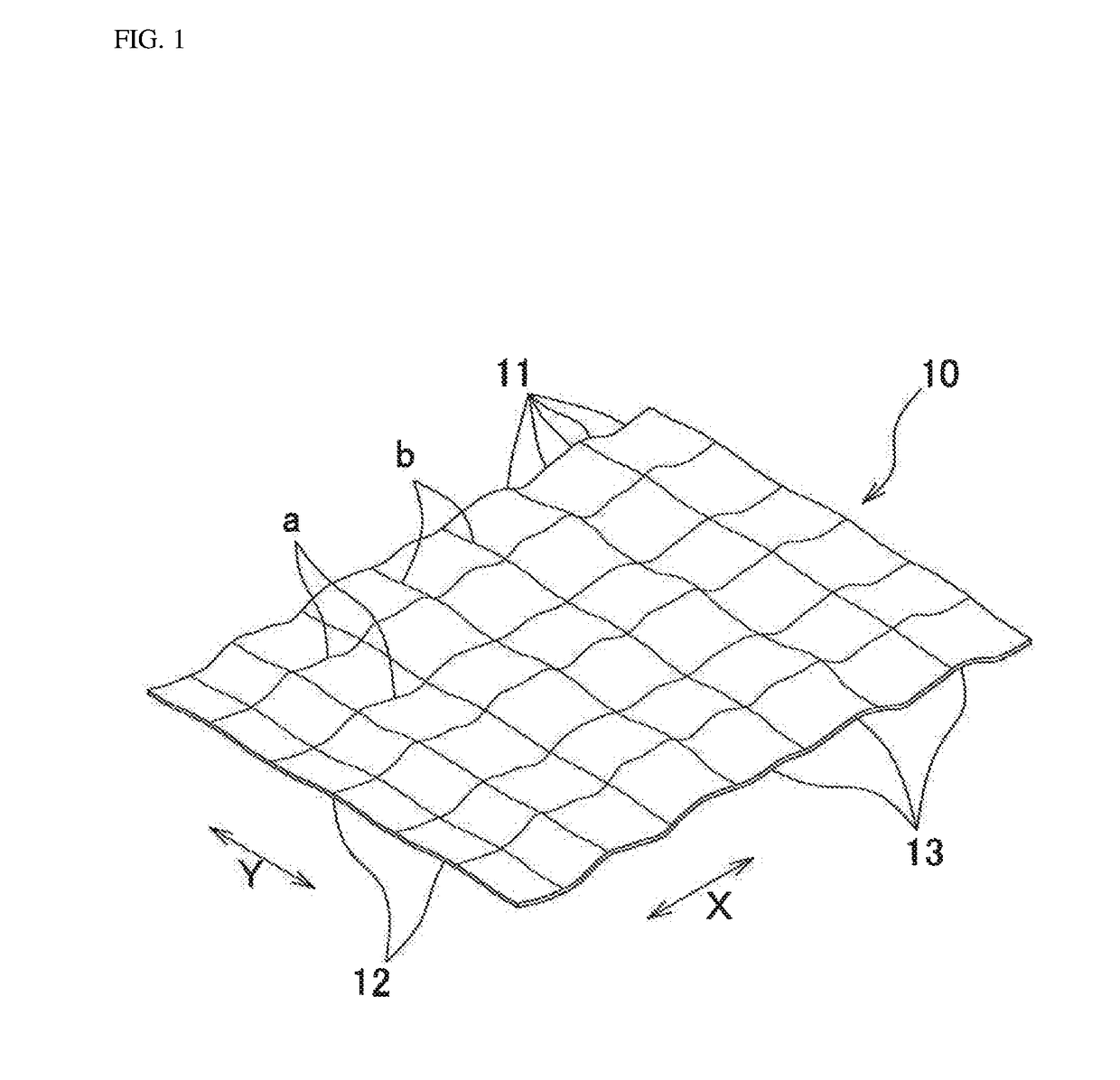
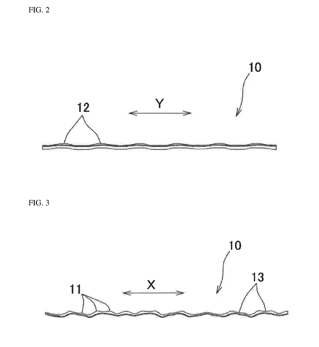
[0036]As illustrated in FIGS. 1 to 3, a metal embossed plate 10 manufactured by a manufacturing method of the present invention has, on the entire plate, corrugations including combination of a plurality of first corrugated portions 11 formed in a first direction X, a plurality of second corrugated portions 12 formed in a second direction Y approximately orthogonal to the first direction X with a half-height and a pitch longer than those of the first corrugated portions 11, and a plurality of third corrugated portions 13 approximately in the first direction X. Curved lines a and b in the drawings are explanatory auxiliary lines drawn to show high portions and low portions of the corrugated portion.

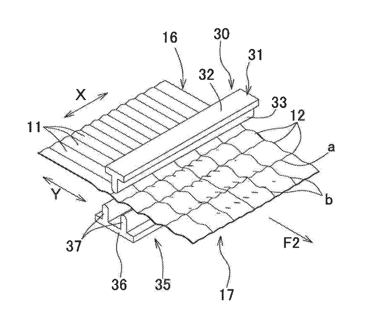
[0037]The method of manufacturing the metal embossed plate 10 includes a first corrugating step illustrated in FIGS. 4 and 5 in which a flat raw metal plate 15 is die-pressed to sequentially for...


PUM

PropertyMeasurementUnit
thicknessaaaaaaaaaa
distanceaaaaaaaaaa
half-height A1aaaaaaaaaa

Abstract

First corrugated portions in a first direction are sequentially formed by die-pressing a raw metal plate. Second corrugated portions formed in a second direction intersecting the first direction are sequentially formed by die-pressing a primary formed plate having the first corrugated portions using elongate projections, so that each of the second corrugated portion has a half-height and a pitch larger than those of each of the first corrugated portion. Third corrugated portions formed approximately in the first direction are sequentially formed by die-pressing a secondary formed plate having the second corrugated portions using elongate projections, so that each of the third corrugated portions has a half-height and a pitch larger than those of the first corrugated portion.

Description

BACKGROUND OF THE INVENTION(1) Field of the Invention[0001]The present invention relates to a metal embossed plate that can suitably be used as a covering member for covering an exhaust part of a road vehicle, an exhaust part covering member of a road vehicle using the metal embossed plate, and a method of manufacturing the metal embossed plate.(2) Description of Related Art[0002]Fuel consumption rises as a weight of a road vehicle increases. Requirements for fuel consumption are becoming severer year by year along with the requirements for CO2 emission. Reduction in the weight of the road vehicle is definitely needed. Meanwhile, road vehicles are becoming heavier for various reasons, such as requirements of crash safety standards for higher strength against offset crash and the increase in the number of devices installed for improving comfort of a road vehicle. To reduce a weight of a part of a road vehicle, use of aluminum alloy materials (aluminum materials), which have high adva...

Claims


Application Information

Patent Timeline
Patent Type & Authority Applications(United States)
IPC IPC(8): B21D13/02
CPCB21D13/02B21D53/88
Inventor ABE, YOSHITAKA
Owner KOKUSAN BUHIN INDS
Why Eureka
Try Eureka