Die insert for extruder

a technology of extruder and die insert, which is applied in the field of die insert for extruder, can solve the problems of deterioration of workability, high installation area, plurality of workers, etc., and achieves the effects of hardly broken or deformed/cracked, easy manufacturing, and simplified shap

Inactive Publication Date: 2005-07-07
TOYO TIRE & RUBBER CO LTD
View PDF3 Cites 43 Cited by
  • Summary
  • Abstract
  • Description
  • Claims
  • Application Information

AI Technical Summary

Benefits of technology

[0011] Moreover, said flat faces are formed to have a step between the surface side and the back side of said cord array. As a result, the die insert is so simplified in shape at its cord exit side that it can be easily manufactured. At the same time, the die insert is so hardly broken or deformed / cracked that it becomes excellent in durability.
[0012] According to the die insert for the extruder of the invention, the cord array prepared by the die insert is fed on its surface side with the rubber when it comes out of the slot exits of the die insert, so that it is topped on its one face without its array pitch being disturbed, such that the individual cords are pushed by the rubber onto the bottoms of the upward open channels formed in the flat faces of the leading end portion of the die insert. After this, the cord array is topped on its back face with the rubber while passing the topping chamber while constraining the motions of the cords, so that the cord array is topped on both faces with the rubber. As a result, the topping operation is not affected by the heterogeneous rubber flow, as exemplified by the fluctuations or pulsations of the amount or pressure of the fed rubber, so that the positions of the cords cannot be disturbed transversely and vertically to provide a topping sheet having a high cord array precision and excellent surface properties. Moreover, the tension, as might otherwise be caused to act on the cords by the flow of the rubber, can be lightened to reduce the residual strain of the cords in the topping sheet thereby to improve the handling of the topping sheet.
[0013] According to the die insert for the extruder of this invention, the motions of the cords at the topping time are effectively suppressed by the simple improvement in the shape of the extruder head thereby to improve the disturbances of the cord array of the topping sheet drastically. Thus, the die insert have an excellent effect in that it can manufacture the topping sheet which is so improved in the cord array precision in the transverse and vertical directions in the sheet as to have excellent homogeneity and quality, thereby to provide the weft-less cord reinforcing material to be properly used in the pneumatic tire, easily and inexpensively. Moreover, the die insert for the extruder of the invention can be practiced by the simple improvement in the structure, thereby to improve the topping precision of the topping sheet without any high cost that might otherwise be required for modifications of another topping jig or the inside of the die head.

Problems solved by technology

However, this calender apparatus is required to include: large-scaled devices in which upstream and downstream of the calender rolls is equipped with a device for letting off rolled cords of the tire fabric and for taking up the topping sheet; and a pretreatment device such as rubber heating rolls, so that it requires a high cost for the facilities and a wide installation area.
This adjustment raises problems that skills are required for keeping the topping precision, and that a plurality of workers are required to deteriorate the workability.
As a result, there arises a problem that the cord array in the topping sheet 23 is irregularly disturbed vertically and transversely in the longitudinal direction of the sheet 23 as shown in FIG. 15.
Other problems are that a small-wave roughness W is made on the surface of the sheet 23 on the basis of the array disturbances of the cords thereby to degrade the surface properties, and that an uneven tension acts on the cords due to the deterioration of the flow of the unvulcanized rubber thereby to leave heterogeneous residual distortions on the individual cords 2 in the topping sheet 23.
Moreover, this homogeneity failure of the topping sheet 23 degrades the quality of the pneumatic tire, that is, affects the durability performance or the uniformity adversely.

Method used


Image

  • Die insert for extruder
  • Die insert for extruder
  • Die insert for extruder

Examples


example

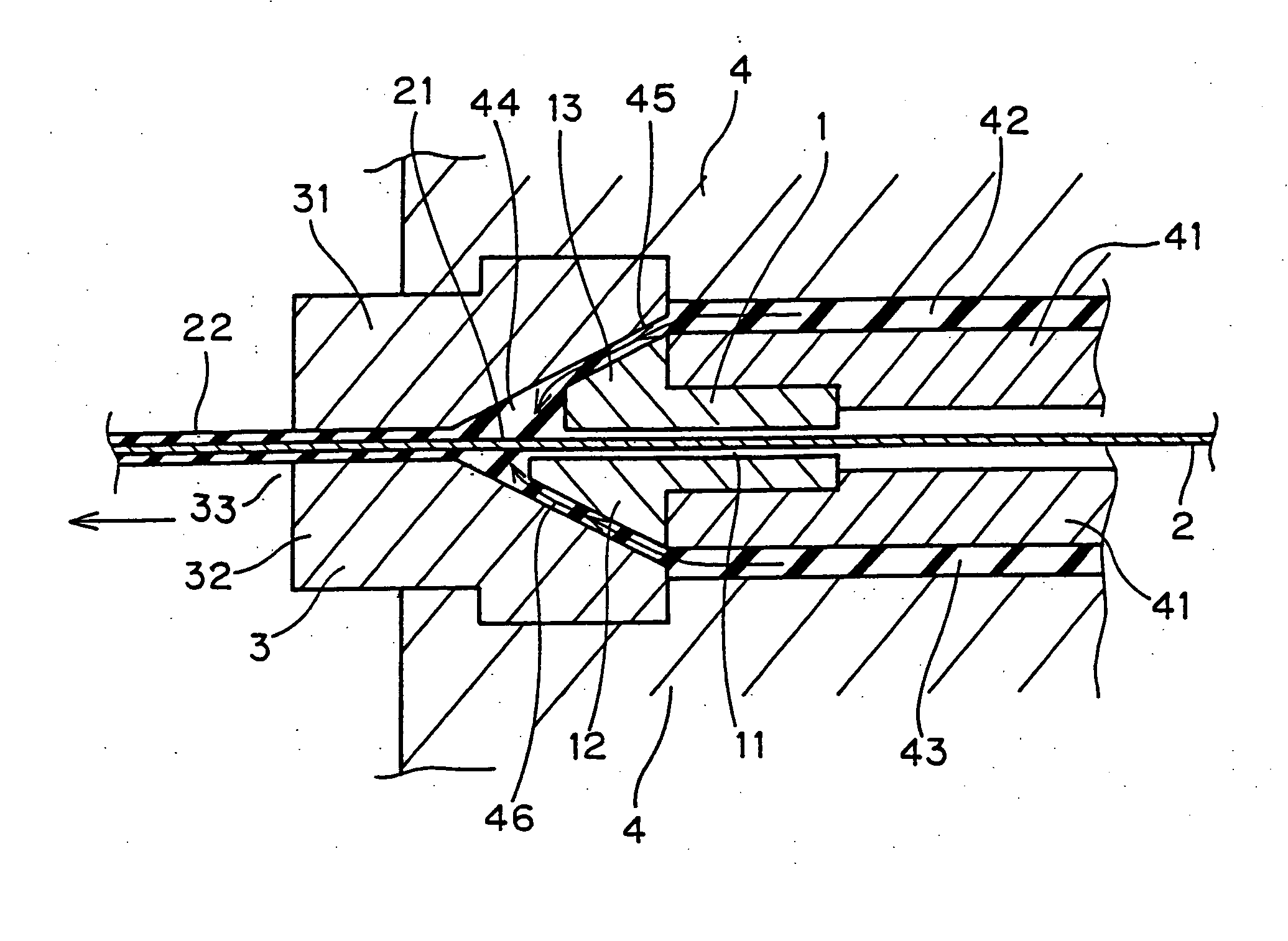
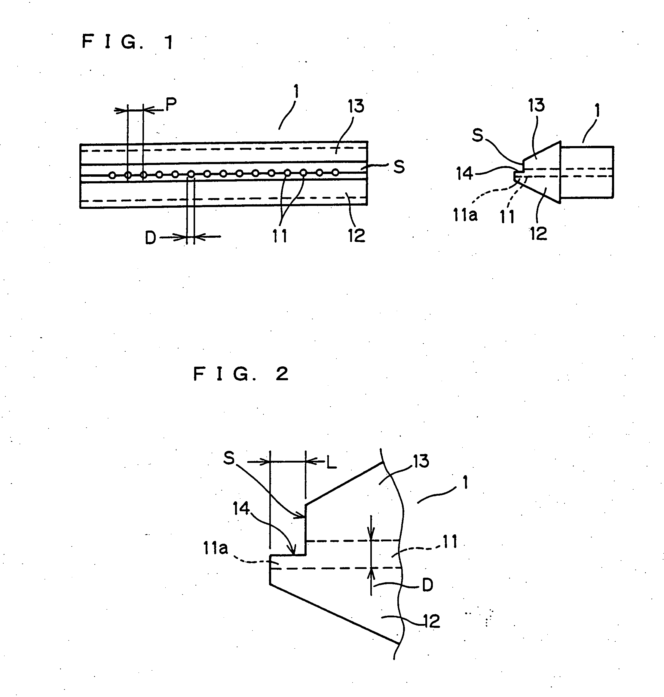
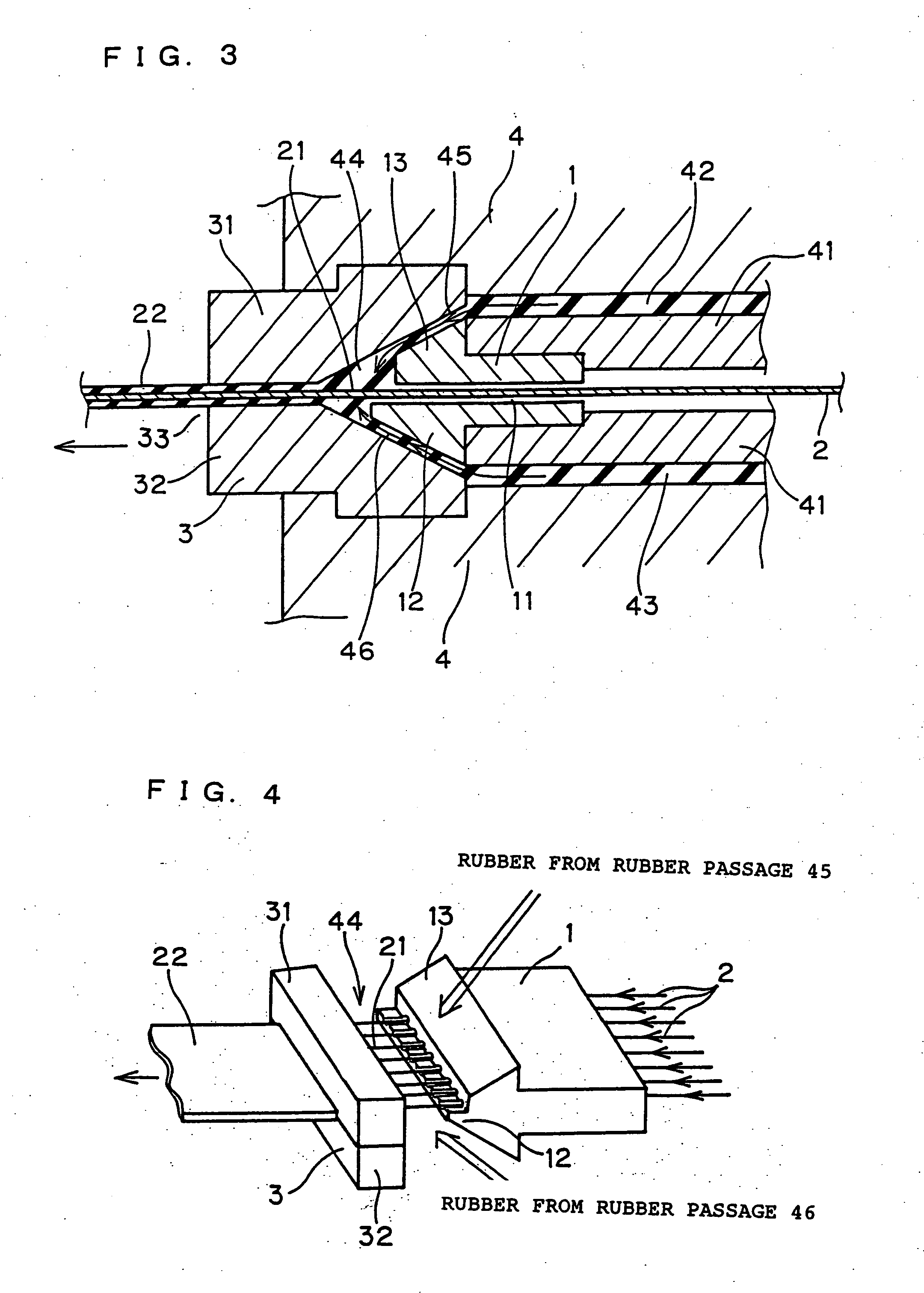
[0055] The die insert was prepared by using treated tire cords (having a cord diameter of 0.67 mm) of polyester of 1,670 dtex / 2, forming 100 cord slots (having the internal diameter D=0.85 mm) at an equal pitch in the die insert shown in FIG. 1, providing a step S, and by changing the ratio of L / D of the open length (L) and the diameter (D) of the channels 11a formed continuously in the identical shape from the cord slots. The die insert thus prepared was arranged in the extruder die head shown in FIG. 3 to manufacture the topping sheet having a topping width of 100 mm and a thickness of 1.1 mm.

[0056] The cord distance d (as referred to FIGS. 6 and 15) of the topping sheet obtained was randomly measured at five portions in the longitudinal direction and at twenty portions in the transverse direction (i.e., the total measurements=100), and a coefficient of variation (%) was determined from the average value and the standard deviation of the measured cord distance values. Moreover, t...


PUM

PropertyMeasurementUnit
diameteraaaaaaaaaa
thicknessaaaaaaaaaa
widthaaaaaaaaaa

Abstract

The invention contemplates to provide a die insert for an extruder, which can suppress the motions of cords at a rubber topping time to improve the disturbance of the cord array pitch of a topping sheet drastically thereby to improve the homogeneity and quality of the topping sheet. In the die insert 1 for the extruder, cord slots 11 are provided at their exit portions with flat faces 14 having channels 11a leading to the cord slots 11 at a die insert leading end portion 12, and the channels 11a for passing a cord array 21 are formed open in the flat faces 14. The channels 11a in the flat faces 14 preferably have a ratio of L/D of 1 to 20 between their open length (L) and diameter (D), and the flat faces 14 are preferably formed to have a step S between the surface side and the back side of the cord array 21.

Description

TECHNICAL FIELD [0001] The present invention relates to a die insert for an extruder, i.e., a topping jig for manufacturing a topping sheet by topping a cord array having a plurality of tire cords arranged at a predetermined pitch, on its surface and back face with rubber without disturbing the array pitch. BACKGROUND ART [0002] In the prior art, a cord reinforcing material constructing the carcass or belt layer of a pneumatic tire is exemplified by a topping sheet which is prepared by topping the two faces of a cord array of a tire fabric having cords arranged in parallel, with unvulcanized rubber. For this topping sheet, there is widely used the so-called calender topping method, in which the cord array is topped through calender rolls arranged in a Z-shape while forming rubber sheets by feeding the rolls with preheated rubber. [0003] However, this calender apparatus is required to include: large-scaled devices in which upstream and downstream of the calender rolls is equipped wit...

Claims


Application Information

Patent Timeline
Patent Type & Authority Applications(United States)
IPC IPC(8): B29C48/07B29C48/30B29C48/305B29D30/38B29K21/00B29L30/00
CPCB29C47/0019B29C47/003B29D2030/381B29C47/14B29C47/027B29C48/07B29C48/12B29C48/156B29C48/305B29C48/34
Inventor HIGASHI, KOUJI
Owner TOYO TIRE & RUBBER CO LTD
Why Eureka
Try Eureka