Electronic Timepiece

a technology of electronic timepieces and timepieces, applied in the field of electronic timepieces, can solve the problems of reducing the probability of successful automatic reception, affecting the noise of the wiring line through which a high-frequency signal, such as a satellite signal, is transmitted, and the reception sensitivity of satellite signals is reduced, so as to improve the probability of successful satellite signal reception and improve the reception sensitivity. , the effect of reliably automatic correction of internal tim

Inactive Publication Date: 2018-10-04
SEIKO EPSON CORP
View PDF0 Cites 2 Cited by
  • Summary
  • Abstract
  • Description
  • Claims
  • Application Information

AI Technical Summary

Benefits of technology

[0033]Also in the aspect of the invention, since the power feeder of the planar antenna is disposed within the first angular range (90-degree angular range from 45 to 135 degrees measured clockwise from the reference line) or in the second angular range (90-degree angular range from 45 to 135 degrees measured counterclockwise from the reference line) with respect to the center of the planar antenna, the directivity of the electronic timepiece in the side surface direction can be set within the 90-degree angular range around the 3-to-9-o'clock direction. The thus configured planar antenna readily receives a signal from a satellite located in the zenith direction, whereby the satellite signal reception sensitivity can be improved. Therefore, even when the electronic timepiece automatically starts satellite signal reception during the user's outdoor walking, the probability of successful satellite signal reception can be increased. When the probability of successful reception increases, the internal time can be reliably automatically corrected. An electronic timepiece that can improve the accuracy of displayed time and provides a high degree of convenience can therefore be provided.

Problems solved by technology

In the automatic reception, however, since the electronic timepiece does not always face the zenith, there is a new problem of a decrease in the reception sensitivity and hence a decrease in the probability of successful automatic reception.
A wiring line through which a high-frequency signal, such as a satellite signal, is transmitted tends to be affected by noise when a straight portion and a bent portion of the wiring line greatly differs from each other in terms of the width of the wiring line pattern, for example, in the case where the wiring line is bend by 90 degrees and the characteristic impedance of the wiring line also greatly changes.

Method used


Image

  • Electronic Timepiece
  • Electronic Timepiece
  • Electronic Timepiece

Examples


first embodiment

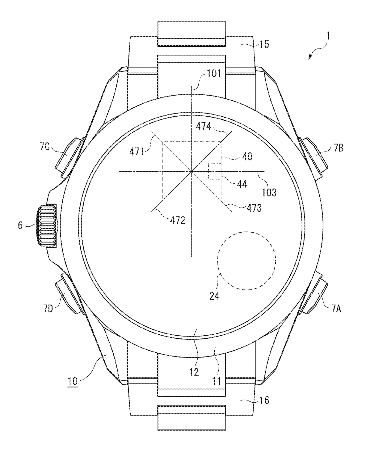
[0055]An electronic timepiece 1 according to a first embodiment of the invention will be described below with reference to the drawings. The present embodiment will be described on the assumption that the side facing a cover glass plate 31 of the electronic timepiece 1 is the front side (upper side) and the side facing a case back 12 is the rear side (lower side).

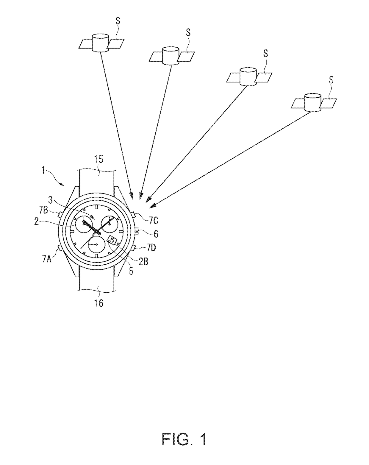
[0056]The electronic timepiece 1 according to the present embodiment is configured to be capable of receiving satellite signals from a plurality of position information satellites S, such as GPS satellites and quasi-zenith satellites, which go along a predetermined orbit around the earth up in the sky, to acquire satellite time information and correcting internal time information, as will be described later. The electronic timepiece 1 further includes, as satellite signal reception capability, not only of a manual reception capability of starting the reception when a user operates a button, but automatic reception capabilit...

second embodiment

[0213]A second embodiment of the invention will next be described with reference to FIG. 16. In the second embodiment, the same or similar configurations as those in the first embodiment have the same reference characters and will not be described.

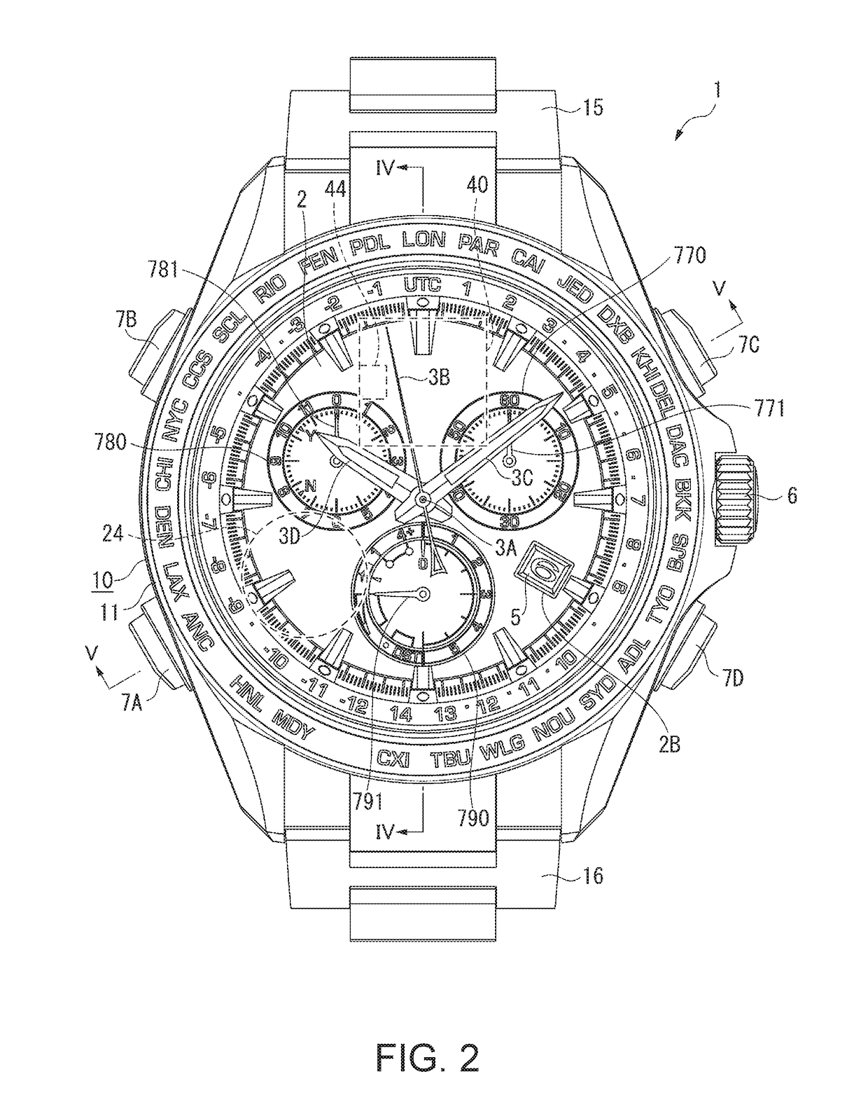
[0214]An electronic timepiece 1B according to the second embodiment differs from the electronic timepiece 1 according to the first embodiment in that a planar antenna 40B is disposed in an inclining attitude. That is, in the electronic timepiece 1 according to the first embodiment, each of the side surfaces 413A to 413D of the planar antenna 40 is disposed so as to be parallel to the first straight line 101, which extends along the 3-to-9-o'clock direction of the electronic timepiece 1, or the second straight line 102, which extends along the 12-to-6-o'clock direction of the electronic timepiece 1.

[0215]On the other hand, in the electronic timepiece 1B according to the second embodiment, the side surfaces 413A to 413D of the planar antenna...


PUM


Abstract

An electronic timepiece includes a planar antenna that receives a circularly polarized wave and a controller that activates the planar antenna. The planar antenna includes an antenna electrode having a degeneracy separator and a power feeder. The power feeder is disposed within a first angular range or a second angular range with respect to the center of the planar antenna. The first angular range is an angular range from a 1.5-o'clock direction to a 4.5-o'clock direction and the second angular range is an angular range from a 7.5-o'clock direction to a 10.5-o'clock direction.

Description

BACKGROUND1. Technical Field[0001]The present invention relates to an electronic timepiece, and particularly to an electronic timepiece including a planar antenna.2. Related Art[0002]A known electronic timepiece includes a planar antenna that receives an electric wave transmitted from a position information satellite such as a GPS (global positioning system) satellite (see JP-A-2015-175738).[0003]The electronic timepiece uses a patch antenna having an electrode shape designed so as to have a reception characteristic that allows reception of a linearly polarized wave (see paragraphs 0037 and 0038 in JP-A-2015-175738). JP-A-2015-175738 describes that a power feeder is disposed at the patch antenna's side close to a metal member to avoid interference due to a metal barrel, a battery, and other metal members so that the reception sensitivity is increased along the patch antenna's sides perpendicular to the side where the power feeder is disposed for improvement in reception sensitivity ...

Claims


Application Information

Patent Timeline
Patent Type & Authority Applications(United States)
IPC IPC(8): G04R60/10G04R20/02H01Q1/27H01Q9/04
CPCG04R60/10G04R20/02H01Q1/273H01Q9/0407H01Q9/0428G04R60/12G04G17/04
Inventor NAKAJIMA, YASUO
Owner SEIKO EPSON CORP
Why Eureka
Try Eureka