
Electronic Device Having an Antenna, Metal Trace(s) and/or Inductor With a Printed Adhesion Promoter Thereon, and Methods of Making and Using the Same

Inactive Publication Date: 2018-10-04
ENSURGE MICROPOWER ASA
View PDF10 Cites 0 Cited by
  • Summary
  • Abstract
  • Description
  • Claims
  • Application Information

AI Technical Summary

Benefits of technology

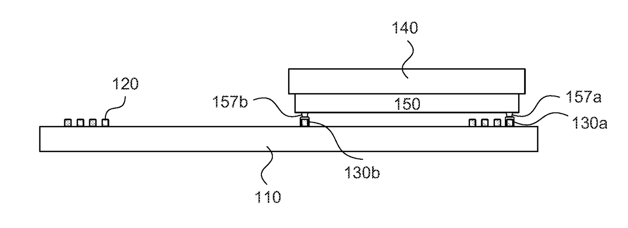
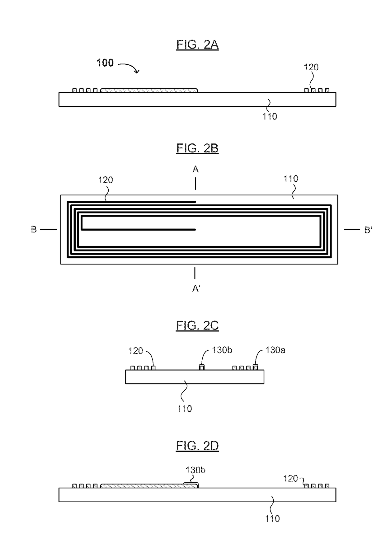
The present invention is related to a method and device for improving the adhesion and electrical connectivity of a first metal layer to electrical connectors on a second substrate, which may be an electronic device. This is achieved by selectively depositing a second metal on at least part of the first metal layer and connecting the electrical connectors to the second metal. This results in smoother and more reliable attachment of electronic components to the antenna, metal traces, and / or inductor on the device, while also reducing processing time and cost. The invention is compatible with various attachment techniques and can be used without the need for an organic copper protector or an anisotropic conductive paste.

Problems solved by technology

However, methods of assembling an aluminum antenna or trace to an integrated circuit or a discrete device (which may be on another substrate) is generally limited to techniques that use stud bumps and / or anisotropic conductive paste (ACP).
Conventional printed backplanes may not meet resistivity requirements for high quality (Q) near field communication (NFC) labels, due to their limited thickness.
However, the method of assembling an IC and a backplane with an aluminum trace is limited to the use of stud bumps and / or ACPs.
However, copper is relatively expensive and is not compatible with food products.
Although solder is relatively inexpensive and suitable for large volume manufacturing processes, copper and / or plated aluminum involves additional cost.
However, palladium is also expensive, and its use and / or capability as an adhesive material for assembling inexpensive aluminum antennas and / or metal traces to discrete devices or integrated circuits is not known.

Method used


Image

  • Electronic Device Having an Antenna, Metal Trace(s) and/or Inductor With a Printed Adhesion Promoter Thereon, and Methods of Making and Using the Same
  • Electronic Device Having an Antenna, Metal Trace(s) and/or Inductor With a Printed Adhesion Promoter Thereon, and Methods of Making and Using the Same
  • Electronic Device Having an Antenna, Metal Trace(s) and/or Inductor With a Printed Adhesion Promoter Thereon, and Methods of Making and Using the Same

Examples


Embodiment Construction

[0032]Reference will now be made in detail to various embodiments of the invention, examples of which are illustrated in the accompanying drawings. While the invention will be described in conjunction with the following embodiments, it will be understood that the descriptions are not intended to limit the invention to these embodiments. On the contrary, the invention is intended to cover alternatives, modifications and equivalents that may be included within the spirit and scope of the invention. Furthermore, in the following detailed description, numerous specific details are set forth in order to provide a thorough understanding of the present invention. However, it will be readily apparent to one skilled in the art that the present invention may be practiced without these specific details. In other instances, well-known methods, procedures, components, and materials have not been described in detail so as not to unnecessarily obscure aspects of the present invention.

[0033]The tec...


PUM


Abstract

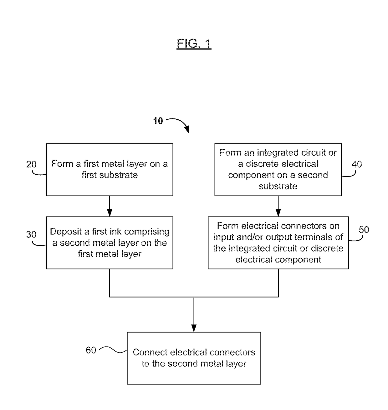
An electronic device and methods of manufacturing the same are disclosed. One method of manufacturing the electronic device includes forming a first metal layer on a first substrate, forming an electrical device on a second substrate, forming electrical connectors on input and / or output terminals of the electrical device, selectively depositing a second metal on at least part of the first metal layer, and electrically connecting the electrical connectors to the first metal layer by contacting the electrical connectors to the second metal. The second metal is different from the first metal. The second metal improves adhesion and / or electrical connectivity of the first metal layer to the electrical connectors on the electrical device.

Description

CROSS REFERENCE TO RELATED APPLICATION[0001]This application claims the benefit of U.S. Provisional Pat. Appl. No. 62 / 238,045, filed on Oct. 6, 2015, incorporated herein by reference as if fully set forth herein.FIELD OF THE INVENTION[0002]The present invention generally relates to the field(s) of printed and / or thin film electronic devices, and in some embodiments, to wireless communications and wireless devices. Embodiments of the present invention pertain to radio frequency (RF and / or RFID), near field communication (NFC), high frequency (HF), very high frequency (VHF), ultra high frequency (UHF), and electronic article surveillance (EAS) tags and devices having a layer of palladium or other adhesion-promoting metal or alloy printed on an antenna, metal trace(s), and / or inductor to improve adhesion, electrical connectivity, and / or attachment of the antenna, metal trace(s), and / or inductor to other electrical circuitry in the tag or device, and methods of manufacturing and using t...

Claims


Application Information

Patent Timeline
IPC IPC(8): G06K19/07H01Q1/22H01Q7/00H05K1/16H05K3/12H05K3/36G08B13/24
CPCG06K19/07H01Q1/2225H01Q7/005H05K1/16H05K3/12H05K3/36G08B13/24H05K2201/0154H05K2201/10098H05K2203/0709H05K3/182H05K3/247H05K2201/10015G08B13/2437G08B13/244G08B13/2442G06K19/067G06K19/07722G06K19/07749G06K19/07783
Inventor TAKASHIMA, MAOBOYD, JACOBCHANDRA, ADITI
Owner ENSURGE MICROPOWER ASA
Learn More