
Biochip testing system

Inactive Publication Date: 2002-10-17
DIGITALGENE BIOSCI
View PDF0 Cites 16 Cited by
  • Summary
  • Abstract
  • Description
  • Claims
  • Application Information

AI Technical Summary

Benefits of technology

[0026] The other object of the invention is to provide a biochip testing system, where the light, after passing through or reflect from a biochip, can be directly received by a light receiver, and the variation of light can be directly converted into corresponding data or image for analysis, such that the cost and processing time can be reduced, and the testing efficiency can be further improved.

Problems solved by technology

After forming the biochip, how to obtain the desired information from the biochip is another important issue.
Spectral filtration is a particularly important issue because most commonly used fluors have a small Stoke's shift (the difference in wavelength between the excitation and emission maxima of a fluorochrome), which makes the effective separation of excitation and emission light difficult.
Isotope label indication method though has the advantage of high signal strength, however, its operator requires special operating license and the waste derived therefrom is hard to process.
Therefore, the cost of the isotope label indication method is high and thus it is not popular.
The isotope label indication method is used in only the research rooms sponsored by national academy or university, and is not suitable for commercial use.
In addition, because the radiative strength is high, it is easy to cause a phenomenon of interference between two testing points when the testing probe is closely to each other.
Accordingly, the isotope label indication method is inappropriate to be used in high-density biochips.
However, the disadvantage of the fluorescent indication method is that it is apt to be interfered by the background noise, and thus a confocal laser scanner which may radiate high power is inevitably used to read signal generated therefrom.
The confocal laser is very expensive so that is inappropriate to be commercially used.
However, because it is required for the confocal laser scanner to use two or more laser heads together with a confocal system so as to form confocal to test biochip, the test path thereof is rather long, and the volume also rather large, which cause the increase of cost.
Therefore, in view of commercialization, the confocal laser scanner is improper for use in the testing of personalized biochip.
There are limitations to laser systems, for example, power and wavelength change as a function of temperature in both diode and solid-state lasers.
Because of special and expensive scanners, peripherals, diagnostic kits, and analytic software being required in the process as well as the cost of photolithographic mask being so great, the method is still not a popular one.
Non-contact, drop-on-demand, high-density ink-jet printing array also costs too much and has a low resolution.
Furthermore, refining of plastic fiber function has reduced the price of optical fiber.
When a test does not need too many testing items or has to combine different kinds of testing items, mass production process will not work, but optical fiber array could.
Besides, because of its uncomplicated process and better resolution, the cost of optical fiber array could be cut down.
Images, formerly, could not be carried over conventional optical fibers, as the light signals became mixed and spatial resolution was not preserved.
There still are several disadvantages, thought bead-based fiber-optic arrays are rather simple to prepare.
Furthermore, single-base mismatches between the probe and target could be detected if adjusting the stringency with either temperature or solvent.

Method used


Image

  • Biochip testing system
  • Biochip testing system
  • Biochip testing system

Examples


first embodiment

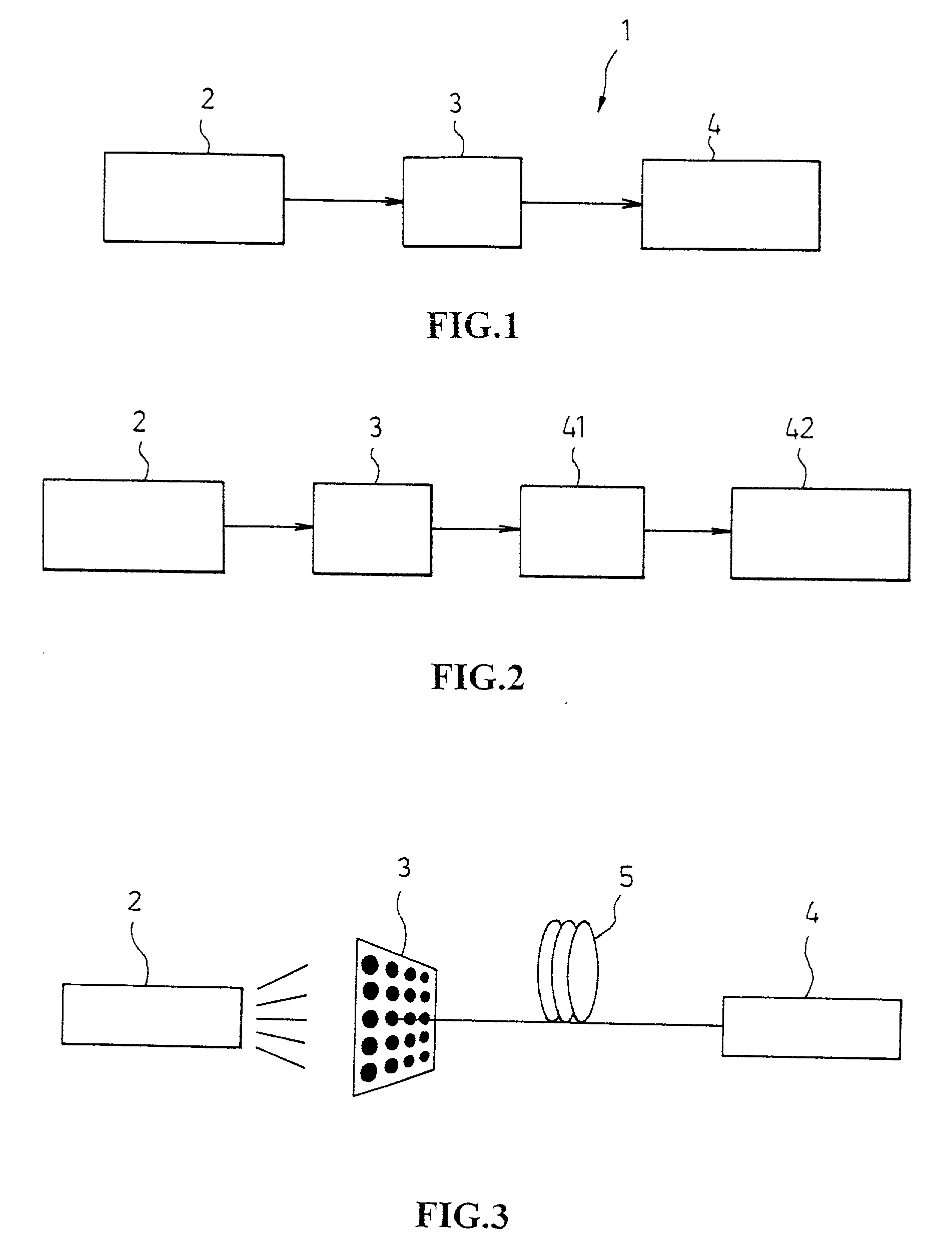
[0053] In the invention, because the light transmitter 2 can directly emit light to the biochip 7, a testing result of the biochip 7 can be obtained through analyzing the light received on the light receiver 4. Therefore, the biochip testing system of the invention not only can radiate a light having high power without attenuation, but also has high resolution and low cost, which thus is suitable for use as personalized biochip testing system.

[0054] In the case that the biochip 7 is non-transparent, the light transmitter 2 and the light receiver 4 may be arranged on the same side with respect to the biochip 7, so as to obtain the variation of light through light reflection.

[0055] FIG. 2 shows the block diagram of the biochip testing system according to the second embodiment of the invention. In FIG. 2, the light receiver 4 includes a photoelectric converter 41 and a signal-processing unit 42. In the second embodiment, when an electronic signal is applied, the electronic signal may b...

second embodiment

[0056] In the invention, because the light receiver 4 further includes a photoelectric converter 41 and a signal processing unit 42, what can be used as a signal source is not limited to a light source, and an electronic signal can also be used.

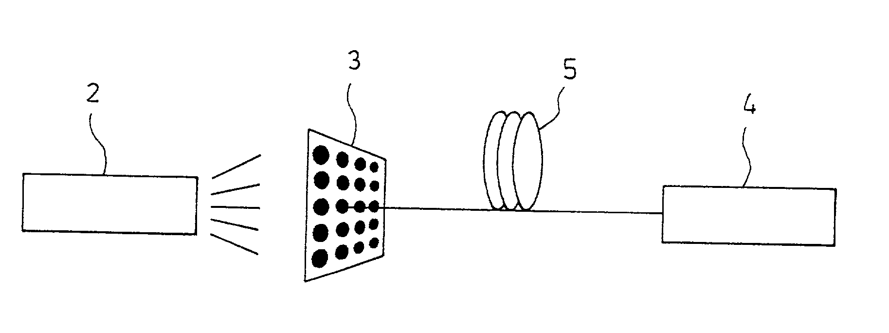
[0057] FIG. 3 shows the block diagram of the biochip testing system according to the third embodiment of the invention. Referring to FIG. 3, the differences between the third embodiment and the first embodiment is that the biochip 7 used in the third embodiment is an optical fiber biochip. The optical fiber biochip is formed by gathering a plurality of optical fibers and coating a biological reagent on one end of each optical fiber.

third embodiment

[0058] In the third embodiment, because the light signal is transmitted through the optical fiber 5, the power of the light signal being transmitted not only does not have attenuation, but also the resolution thereof is higher. Further, owing to the use of optical fiber biochip, the sizes of all testing points are the same and no interference will occur between the testing points.

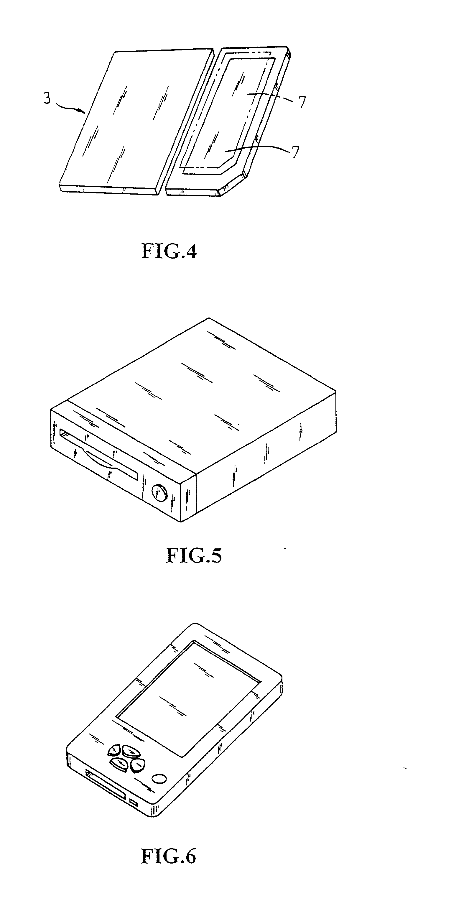
[0059] In addition, in the embodiments of the invention, the biochip 7 is detachably adhered on the recording medium 3, where the recording medium 3 can be a disc as shown in FIG. 4. The other type of recording medium, such as an optical disc, smart card, etc., can also be used as the recording medium 3.

[0060] Furthermore, in the biochip testing system 1 of the invention, the light receiver 4 is arranged in a single one or in matrix, for one-by-one or in array sensoring each testing points where the signal is transmitted from the light transmitter 2 passing through or reflect from each cell of the biochip 7...


PUM

PropertyMeasurementUnit
Currentaaaaaaaaaa
Transparencyaaaaaaaaaa

Abstract

The invention relates to a biochip testing system for testing the status of a biochip carried on a recording medium. The biochip testing system comprises: a light transmitter; a biochip including a plurality of cells coated with biological reagents; a recording medium for carrying the biochip; and a light receiver for receiving the light from the light transmitter passing through or reflect from the biochip. The invention also relates to a recording medium having the biochip thereon, and a personal digital biochip assistant having the biochip testing system.

Description

[0001] 1. Field of the Invention[0002] The invention relates to a biochip testing system for testing the status of a biochip carried on a recording medium. More specifically, the biochip testing system comprises: a light transmitter; a biochip having a plurality of cells each coated with a biological reagent; a recording medium for carrying the biochip; and a light receiver for receiving the light from the light transmitter passing through or reflect from the biochip and sensor. The invention also relates to a recording medium having the biochip thereon, and a personal digital biochip assistant having the biochip testing system.[0003] 2. Description of Prior Arts[0004] Recently, biochips play an important role in gene engineering and against diseases. It's not only because of the variety of applications including diagnostics, drug screening, forensics, herb screening, and plant biology etc, but also because of the variety of sciences and technologies involved in the development proc...

Claims


Application Information

Patent Timeline
IPC IPC(8): G01N21/25
CPCB01J2219/00585B01J2219/00596B01J2219/00605B01J2219/0061G01N21/253B01J2219/00621B01J2219/00659B01J2219/00702B01J2219/00612
Inventor CHEN, GUAN-TINGLAI, MINDA
Owner DIGITALGENE BIOSCI
Learn More