Device for storage, mixing and dispensing of a bone cement, and pertinent method

a technology for mixing and dispensing devices and bone cement, which is applied in the direction of osteosynthesis devices, transportation and packaging, infusion syringes, etc., can solve the problems of inability to mix cement powders with said devices, disturbance of surgical procedures, and unsatisfactory odor, so as to reduce radiation exposure of physicians, minimize the effect of unpleasant odor and maximum simplified operation of the devi

Active Publication Date: 2018-10-11
HERAEUS MEDICAL
View PDF0 Cites 24 Cited by
  • Summary
  • Abstract
  • Description
  • Claims
  • Application Information

AI Technical Summary

Benefits of technology

[0026]Accordingly, it is also an object of the invention to develop a device for storage and mixing of cement powder and monomer liquid, whereby the PMMA bone cement dough produced by mixing the cement components is preferably intended for augmentation of fractured vertebral bodies. The handling of the device is to be maximally simplified in order to basically prevent user errors resulting from assembly steps taking place incorrectly. The medical user is to be enabled, after taking it out of a packaging, to connect the device to an extrusion device and to subsequently manually actuate said facility. Additional assembly and working steps are to be omitted due to the design of the device. The device is to ensure the secure storage of cement powder and monomer liquid in separate compartments such that any inadvertent mixing of the cement components during storage of the device is excluded. The device is to allow for sterilization with ethylene oxide gas. For this purpose, the cement powder stored in the device must be accessible to ethylene oxide. It shall be feasible to activate the device with the aid of a manually driven extrusion device in the OR such that, after form-fitting or force-locked connection of the device to the extrusion device, the axially propellable rod of the extrusion device acts on the device due to the extrusion device being actuated and opens the monomer liquid container and subsequently, when the rod moves further, transfers the monomer liquid into the cement powder. The mixing of the monomer liquid and the cement powder is to take place without the aid of a mixer that is to be moved manually from outside. Just the forward motion of the rod of the extrusion device, if possible, is to effect the opening of the monomer liquid container, the subsequent monomer transfer into the cement powder, and the mixing of the cement components while forming the bone cement dough. Moreover, it is important for application in vertebroplasty that a suitable connector or a connector with a hose, through which the bone cement dough produced can be applied, can be attached to the device. It is also important for this kind of application to design the plunger for dispensing the bone cement dough thus produced appropriately such that the pressure acting on the plunger upon the use of a manual extrusion device is sufficiently high such that the bone cement dough can be extruded through a plastic hose with an internal diameter of 3 mm over a distance of at least 20 cm.
[0135]The particular advantage of the device according to the invention is that manually driven extrusion devices can be used to extrude a two-component spine cement and / or the bone cement dough for vertebroplasty through a thin hose into the trocar. The augmentation of vertebral bodies takes place under permanent X-ray control. Having a hose between the trocar and the applicator allows the physician to not have to work with his or her hands within the range of the X-rays. No complex expensive hydraulic application devices are required in this context.

Problems solved by technology

This can lead to air bubbles being enclosed in the bone cement dough, which can have a negative effect on the mechanical properties of the cured bone cement.
Any confusion of the working steps can lead to failure of the mixing device and can therefore cause a disturbance in the surgical procedure.
It is a disadvantage of the system that cement powders, which swell quickly due to the monomer liquid, cannot be mixed with said device, because the rapidly swelling cement powder particles form a gel-like barrier of approximately 1 to 2 cm after ingress of the monomer liquid into the cement powder and impede the migration of the monomer liquid through the entire cement powder.
Moreover, conventional cement powders show a phenomenon, which is that the cement powder particles are wetted only poorly by methylmethacrylate due to the difference in surface energies.
Moreover, it cannot be excluded that the monomer liquid, exposed to the action of a vacuum, is aspirated through the vacuum connector after the monomer liquid fully penetrates into the cement powder.
In this case, an insufficient amount of monomer liquid for curing by radical polymerization is available and / or the mixing ratio and thus the consistency of the bone cement is changed inadvertently.
Moreover, it is a problem that the air trapped between the cement powder particles is to be displaced by the monomer liquid proceeding from top to bottom, because the air, having a lower specific weight than the monomer liquid, tends to migrate upwards in the cement powder rather than downwards in the direction of the vacuum connector under the force of gravity.
This exertion of a large force is unreasonable for medical users in the operating room or OR.
Said devices can extrude particularly thick pasty masses since their extrusion force is very large in some cases.
However, it is one disadvantage of the use of electrical motors that these motors contain non-ferrous metals and are expensive purchases.
Since the OR area needs to be kept sterile, said devices need to be sterilized with much effort or may even need to be replaced.
The presence of electrical wiring may impede the mobility of the user in the OR.
This necessitates compressed air hoses, which may impede the mobility of the user.
As a result, the parts of the bone cement applicator serving as borders to the bone cement flow (the cartridges, the housing of the mixer, and the hose) are subject to elastic deformation.
This may lead to contamination of the operation room (OR) or of the user with bone cement or an excessive amount of the bone cement is applied inadvertently.
This, in turn, delays the time point after commencement of the propulsion of the dispensing plungers from which the bone cement can actually be applied, which is also undesirable.
This can be counteracted by the use of massive and expensive metallic housing parts.
Said parts need to be cleaned after use and need to be sterilized for further use or need to be recycled with much effort.
Moreover, residual starting components may be released when the cartridges are taken off and may contaminate the OR theater.
However, the system is not suitable for mixing the viscous pasty starting components of PMMA bone cement.

Method used


Image

  • Device for storage, mixing and dispensing of a bone cement, and pertinent method
  • Device for storage, mixing and dispensing of a bone cement, and pertinent method
  • Device for storage, mixing and dispensing of a bone cement, and pertinent method

Examples


first embodiment

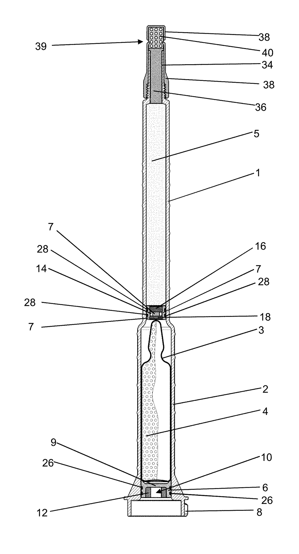
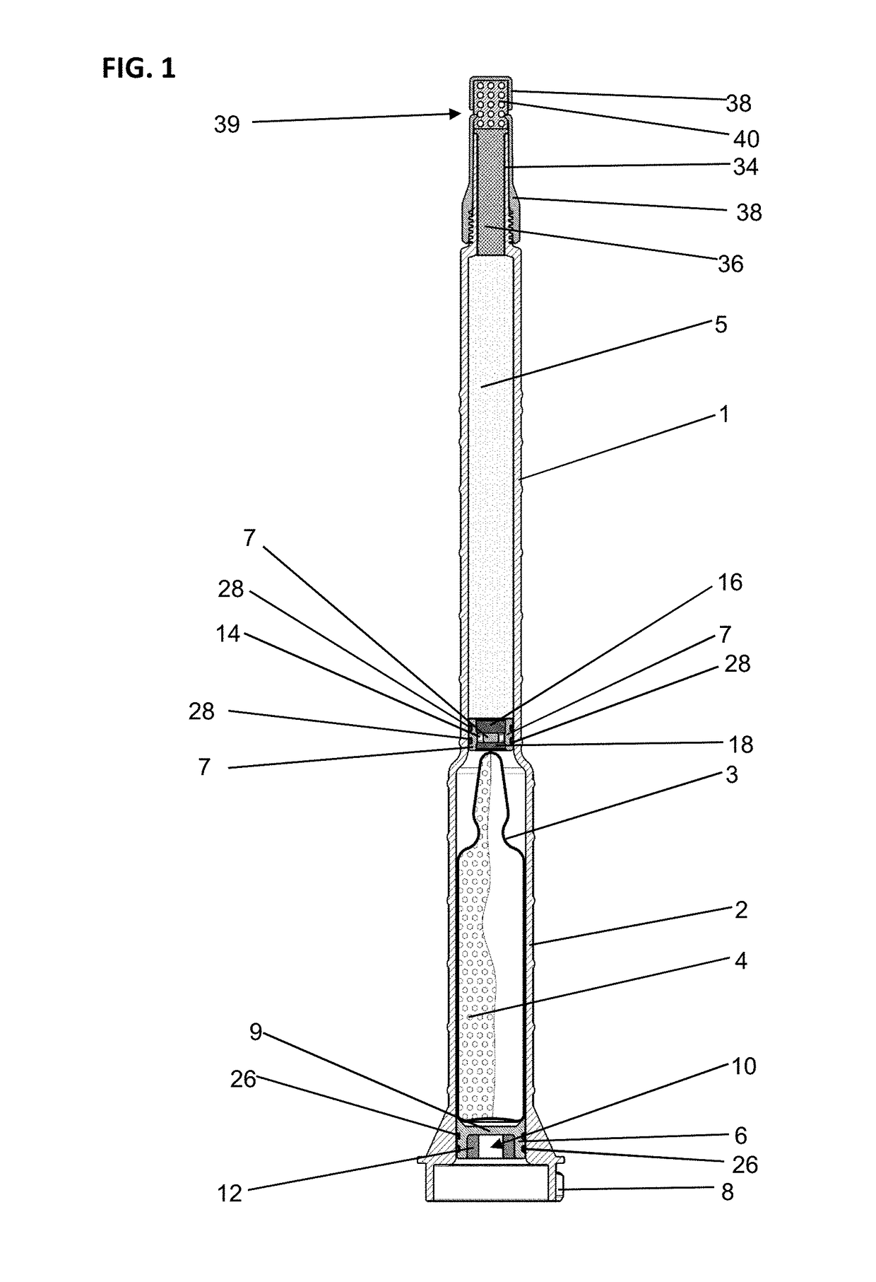
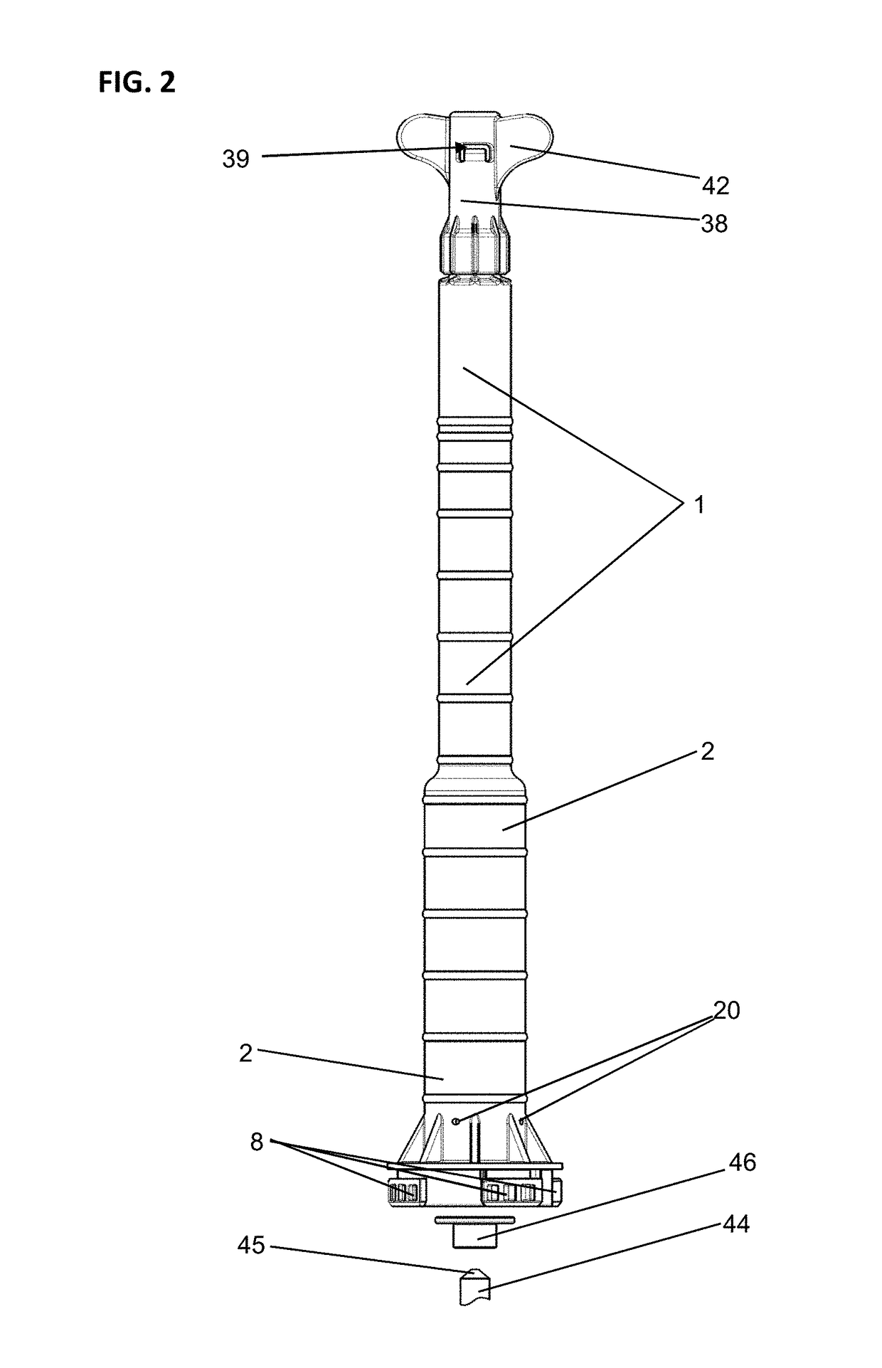
[0195]The trocar 66 is directly connected to the hose 64, but can also be connected to the hose 64 by an adapter. The first embodiment in FIG. 5C shows a variant, in which a connector 72 connects a Luer system adapter 74 via a short hose 76 to the cartridge 1. The connector 72 can be screwed onto the dispensing tube 34 of the cartridge 1 with the aid of wings 78 in the way of a wing screw. For this purpose, the connector 72 comprises a matching internal thread.

[0196]The detail view of the detail magnification according to FIG. 6 of the valve system additionally shows that the tube 59 is connected to the hose 64 by an insert 80, which comprises a channel that aligns with the passage 61. For this purpose, the insert 80 is screwed into the tube 59. In order to ensure a pressure-tight connection, the hose 64 is crimped onto the insert 80 by a metal sleeve 82, and the tube 59 is sealed with respect to the internal wall of the dispensing tube 34 by two circumferential seals 84. The unders...

second embodiment

[0222]In this state, the cap 238 with the pore filter 236 and the foam 240 is unscrewed and, instead, an extended dispensing opening is screwed onto the dispensing tube 234. The extended dispensing opening can preferably comprise a three-way valve analogous to the first or Likewise, a hose and / or a trocar can be connected to the dispensing tube 234. The rod 44 is driven further and, in the process, its tip 45 punctures the feed plunger 206, which is blocked by the step between the cartridge 201 and the receptacle 202, at the predetermined breakage site 209 and, if applicable, punctures the cap 46 earlier. The shreds and / or residues of the film bag 203 are pushed aside in this context. The tip 45 of the rod 44 hits against the dispensing plunger 207.

[0223]The bone cement dough 54 can be dispensed through the hose 64 and the trocar 66 or through the dispensing tube 234. For this purpose, the dispensing plunger 207 is propelled in the direction of the dispensing tube 234 by the rod 44...


PUM

PropertyMeasurementUnit
forceaaaaaaaaaa
thicknessaaaaaaaaaa
surface areaaaaaaaaaaa

Abstract

A device for storage of a monomer liquid and a cement powder as starting components of a bone cement dough and for mixing the starting components, and for dispensing the mixed bone cement dough. The device includes a receptacle in which a monomer liquid container is arranged and a cartridge containing the cement powder. A feed plunger is arranged in the receptacle. A dispensing plunger is arranged between the monomer liquid container and the cement powder in the cartridge. The feed plunger can be punctured by a rod when motion of the feed plunger is blocked, whereby the dispensing plunger is propelled by propelling the rod further through the blocked and punctured feed plunger.Also provided are an extrusion device for propelling a feed plunger and a dispensing plunger of a device for mixing of a bone cement dough, and a method for the production of a bone cement dough.

Description

RELATED APPLICATION[0001]This application claims priority of German Patent Application No. DE 10 2017 107 569.0 filed on Apr. 7, 2017.TECHNICAL FIELD[0002]The invention relates to a device for storage of a monomer liquid and a cement powder as starting components of a bone cement dough and for mixing of the bone cement dough from the starting components, and for dispensing the mixed bone cement dough.[0003]The invention also relates to an extrusion device for application of said device and to a method for the production of a bone cement dough, in particular of a pasty polymethylmethacrylate bone cement dough.BACKGROUND OF THE INVENTION[0004]The subject matter of the invention specifically is a device for separate storage of the cement powder and the monomer liquid of polymethylmethacrylate (PMMA) bone cements, for subsequent mixing of the cement powder with the monomer liquid in order to produce a bone cement dough, and for dispensing the mixed bone cement dough. The bone cement dou...

Claims


Application Information

Patent Timeline
Patent Type & Authority Applications(United States)
IPC IPC(8): A61B17/88C04B26/06A61L24/06A61L24/02
CPCA61B17/8833C04B26/06A61L24/06A61L24/02C04B2111/00836A61B2017/8838B65D81/32B65D83/0005A61M5/284A61B17/8825A61M2005/31598B01F25/43141B01F33/50112B01F35/7131B01F35/7174
Inventor VOGT, SEBASTIANKLUGE, THOMAS
Owner HERAEUS MEDICAL
Why Eureka
Try Eureka