

Transfer type ink jet recording method and transfer type ink jet recording apparatus
- Summary
- Abstract
- Description
- Claims
- Application Information
AI Technical Summary
Benefits of technology
Problems solved by technology
Method used
Image

Examples
example 1
[0175]A reaction liquid, a glossy layer-forming material-(first resin-) containing liquid and an ink were prepared as shown below. The component amounts with “%” are based on mass unless otherwise noted.
[0176][Preparation of Reaction Liquid]
[0177]Citric acid: 30.0%
[0178]Glycerol: 15.0%
[0179]Nonionic surfactant: 1.0%
[trade name: Acetylenol E100 (manufactured by Kawaken Fine Chemicals)]
[0180]Water: remainder
[0181][Preparation of Glossy Layer-Forming Material-(First Resin-)Containing Liquid 1]
[0182]Resin emulsion of styrene-acrylic copolymer (20% preparation liquid) (first resin): 50.0%
[trade name: SK-202 (manufactured by Saiden Chemical Industry Co., Ltd.)]
(average particle diameter: 180 nm; weight average molecular weight: 100,000; minimum film forming temperature: 85° C.; glass transition temperature: 96° C.)
[0183]Glycerol: 5.0%
[0184]Diethylene glycol: 7.0%
[0185]Nonionic surfactant: 0.5%
[trade name: Acetylenol E100 (manufactured by Kawaken Fine Chemicals)]
[0186]Water: remainder
[0187...
example 2
[0213]The glossy layer-forming material-(first resin-)containing liquid 1 was changed to the following liquid 3, and the reaction liquid and the inks were set in the transfer type ink jet recording apparatus in FIG. 1 in the same manner as in Example 1.
[0214][Preparation of Glossy Layer-Forming Material-(First Resin-)Containing Liquid 3]
[0215]Resin emulsion of styrene-acrylic copolymer (20% preparation liquid): 30.0%
[trade name: KE-1062 (manufactured by Seiko PMC)]
(average particle diameter: 80 nm; weight average molecular weight: 100,000; minimum film forming temperature: 55° C.; glass transition temperature: 96° C.)
[0216]Paraffin wax emulsion: 20.0%
[trade name: AQUACER497 (manufactured by BYK Japan KK)]
(melting point: 60° C.)
[0217]Glycerol: 5.0%
[0218]Diethylene glycol: 7.0%
[0219]Nonionic surfactant: 0.5%
[trade name: Acetylenol E100 (manufactured by Kawaken Fine Chemicals Co., Ltd.)]
[0220]Water: remainder
[0221]In the example, the minimum film forming temperature of the glossy layer...
example 3
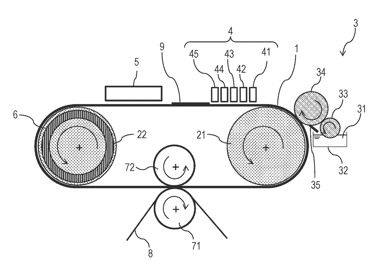
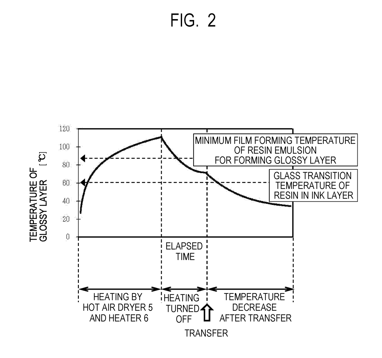
[0223]As shown in FIG. 3, a noncontact type temperature sensor (infrared thermometer) 10 for measuring the temperature of a glossy layer was provided in a section from turning-off of the contact of a heater 6 for heating to a transfer roller 71. The glossy layer is present between the image formation surface of the transfer member 1 and the ink layer, but the ink layer has an extremely small thickness of several to several tens of micrometers. Hence, the temperature of the ink layer on the outermost surface of the intermediate image measured by the noncontact type temperature sensor 10 can be regarded as the temperature of the glossy layer.
[0224]The temperature sensor 10 is provided in order to ascertain the temperature of the resin contained in a glossy layer at the time of transfer. In other words, the sensor is provided in order to ascertain that the temperature is within an appropriate temperature range of lower than the glass transition temperature of the first resin contained ...
PUM
| Property | Measurement | Unit |
|---|---|---|
| Glass transition temperature | aaaaa | aaaaa |
| Glass transition temperature | aaaaa | aaaaa |
| Glass transition temperature | aaaaa | aaaaa |
Abstract
Description
Claims
Application Information