Belt pulley decoupler with sliding guide housing

A technology of belt pulley and decoupler, which is applied to components with teeth, belts/chains/gears, hoisting devices, etc., to achieve the effect of simplified assembly and simple structure

Active Publication Date: 2020-09-18
SCHAEFFLER TECH AG & CO KG
View PDF9 Cites 0 Cited by
  • Summary
  • Abstract
  • Description
  • Claims
  • Application Information

AI Technical Summary

Problems solved by technology

The current preference is to harden the cover, but keep the pulley "soft"

Method used


Image

  • Belt pulley decoupler with sliding guide housing

Examples


Embodiment Construction

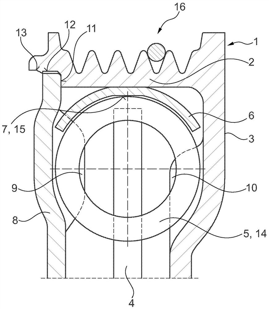
[0041] figure 1 A belt pulley decoupler 1 constructed from several elements is shown. The belt receiving area 2 is characterized in that it is the radially outer area of ​​the belt pulley 3 . The pulley 3 is adapted to receive the ring. A drive flange 4 is arranged radially inside the belt receiving area 2 . An elastic element 5 , ie a spring, is arranged between the driving flange 4 and the belt pulley 3 . The elastic element 5 connects the drive flange 4 to the pulley 3 in a torque-transmitting and vibration-damping manner.

[0042] Another core component of the assembly is the sliding guide housing 6 . The slide housing 6 has a defined contact surface 7 which contacts the spring element 5 . The components of the cover 8 are likewise central. Cover 8 is a component that spatially isolates belt pulley decoupler 1 from the environment. A lubricating material, such as grease, can be provided in the pulley isolator by means of the cover without the lubricating material co...


PUM


Abstract

The invention relates to a pulley decoupler (1) for damping rotational irregularities, comprising: a pulley (3), which has a belt-accommodating region (2); a drive flange (4), which is arranged radially inside of the belt-accommodating region (2); and an elastic element (5), which is arranged between the pulley (3) and the drive flange (4) and connects the drive flange (4) to the pulley (3) in a torque-transmitting and vibration-damped manner; wherein a sliding shell (6) is arranged radially inside of the belt-accommodating region (2) and is fixed to the pulley, the radially inner face of said sliding shell forming a contact surface (7) which supports the elastic element (5).

Description

technical field [0001] The invention relates to a belt pulley decoupler for suppressing rotational inhomogeneities, with a pulley having a belt receiving area for force-transmitting contact with an endless traction element, for example (toothed) belt; and a cover mounted on the pulley, wherein the pulley is prepared for the introduction or delivery of torque; a driving flange, preferably separate from the belt pulley, for the introduction or introduction of torque, Wherein, the driving flange is arranged, for example, radially inside the belt receiving area; and an elastic element, such as a spring, is arranged between the belt pulley and the driving flange, wherein the elastic element makes the driving flange and the belt pulley transmit Torque-proof and vibration-damping connection. Background technique [0002] A device of this type is known from the international publication WO 2012 / 075984 A1. This publication discloses a pulley damper for damping torsional vibrations ...

Claims


Application Information

Patent Timeline
Patent Type & Authority Patents(China)
IPC IPC(8): F16H55/36
CPCF16H55/36F16H2055/366
Inventor B·施托贝尔A·罗泽
Owner SCHAEFFLER TECH AG & CO KG
Why Eureka
Try Eureka