Servicing a top drive device of a wellbore drilling installation

a technology of top drive device and wellbore drilling, which is applied in the direction of drilling rods, drilling pipes, rotary drilling, etc., can solve the problems of equipment failure, failure of top drive device, and high cost of drilling installation downtime, so as to reduce downtime and enhance serviceability of top drive

Active Publication Date: 2018-10-18
ITREC BV
View PDF4 Cites 10 Cited by
  • Summary
  • Abstract
  • Description
  • Claims
  • Application Information

AI Technical Summary

Benefits of technology

[0020]The inventive method of the first aspect of the invention is based on the insight that by facilitating the removal of a top drive motor by means of the motion arm whilst the rest of the top drive device remains attached to the trolley the time and effort needed for any servicing can be greatly reduced.
[0069]As explained with reference to the first aspect of the invention, serviceability of such a trolley and top drive combination can be enhanced by providing a rotatable head clamp assembly with a thrust bearing that absorbs the vertical load of the drill string in the firing line, wherein the rotatable head clamp assembly is supported by the frame below the top drive device. This arrangement allows to dispense with this thrust bearing in the top drive device itself, e.g. allowing for a light thrust bearing in the top drive device or the entire absence of a thrust bearing in the top drive device. If present in the top drive device, any thrust bearing will be significantly less loaded during operational use and thereby less prone to wear compared to existing designs. Also, as explained herein, the thrust bearing in the rotatable head clamp assembly can be accessed easier compared to such a bearing located in the gearbox or transmission housing of the top drive device. In an embodiment the rotatable head clamp assembly is readily exchangeable as a unit, allowing decoupling of the unit from the frame or the rest of the frame, e.g. for replacement by a spare rotatable head clamp assembly unit.

Problems solved by technology

In the field, especially in the offshore drilling field, downtime due to equipment failure is considered a major issue.
Whilst a drilling or other wellbore related operation involves the use of numerous pieces of equipment, studies seem to indicate that the top drive device is one of the major contributors to undesirable downtime.
Notwithstanding the efforts made so far to reduce downtime, failures of top drive devices still occur at the expense of very costly downtime of the drilling installation.

Method used


Image

  • Servicing a top drive device of a wellbore drilling installation
  • Servicing a top drive device of a wellbore drilling installation
  • Servicing a top drive device of a wellbore drilling installation

Examples


Embodiment Construction

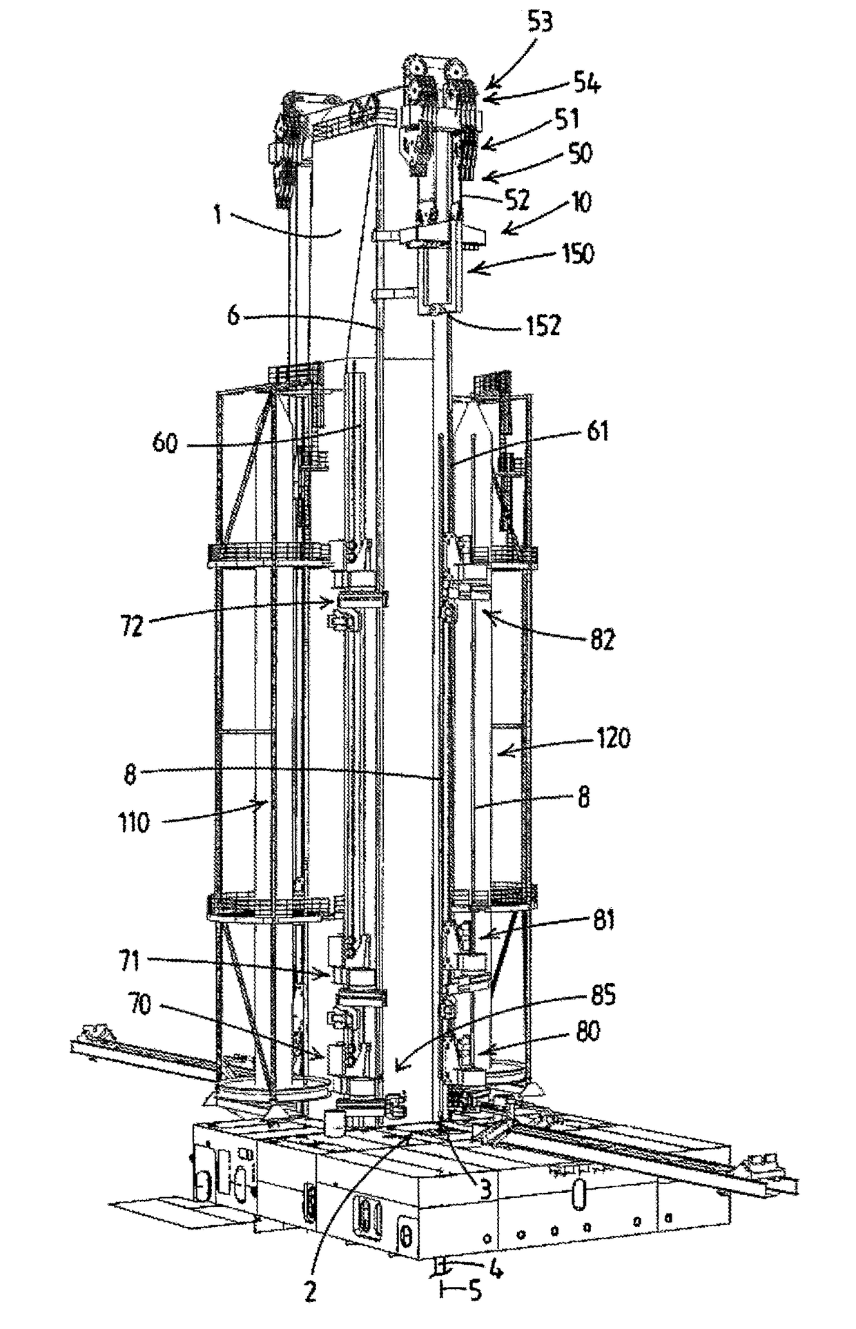
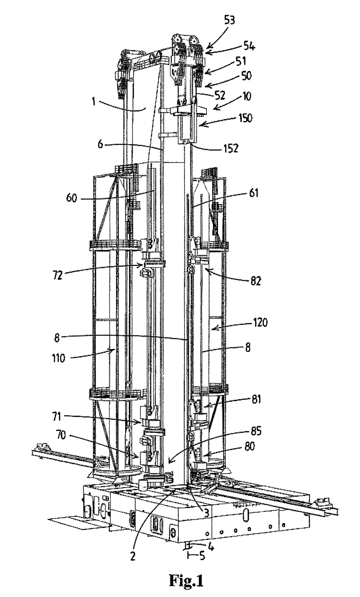
[0146]FIG. 1 shows a wellbore drilling installation with a top drive device according to the invention. It is envisaged that the depicted installation is part of an offshore drilling vessel for performing offshore drilling and / or other wellbore related activities, e.g. well intervention.

[0147]As will be clear from the following description FIG. 1 only shows the trolley with the top drive device removed for reasons of clarity. Other figures do show the ensemble of the trolley and the top drive device.

[0148]The installation comprises a drilling tower 1 that is here embodied as a mast with a closed contoured steel structure with at least one firing line outside of the mast itself. For example the mast is arranged adjacent a moonpool of a drilling vessel, or over a larger moonpool with two firing lines along opposed outer faces of the mast 1 as is known in the art.

[0149]In an alternative design the drilling tower is embodied as a derrick with the firing line within the structure of derr...


PUM


Abstract

A method for servicing a top drive device of a wellbore drilling installation. The installation comprises a drilling tower, a drill floor having a well center through which a drilling tubulars string can pass along a firing line. A trolley is guided along a vertical trolley rail. A top drive device is attached to the trolley and comprises one or more top drive. A motion arm assembly comprises a base and an extensible and retractable motion arm, wherein the base is guided by a vertical motion arm rail. The motion arm has an operative reach that encompasses the firing line. The motion arm assembly is adapted to support at least one of a well center tool, e.g. an iron roughneck tool and a tubular gripper member, and allowing to bring said well center tool or tubular gripper member in the firing line. In order to remove a top drive motor from the top drive device whilst the rest of the top drive device remains attached to the trolley, the motion arm assembly and / or the trolley are operated so that the top drive motor is within the operative reach of the motion arm, the motion arm is operated to reach the top drive motor and the top drive motor is connected to the motion arm, and then the motion arm is used to support and / or lift, lower said top drive motor upon disconnection thereof from the rest of the top drive device.

Description

FIELD OF THE INVENTION[0001]The present invention relates to the servicing a top drive device of a wellbore drilling installation, e.g. mounted on an offshore drilling vessel.BACKGROUND OF THE INVENTION[0002]In WO2014 / 182160 an offshore vessel with a wellbore drilling installation is disclosed which comprises:[0003]drilling tower,[0004]a drill floor having a well center through which a drilling tubulars string can pass along a firing line,[0005]at least one vertical trolley rail supported by the drilling tower,[0006]a trolley, said trolley being guided along said at least one vertical trolley rail,[0007]a top drive device attached to the trolley, said top drive device comprising one or more top drive motors, e.g. electric top drive motors, adapted to impart rotary motion to a drilling tubulars string when connected to said top drive device,[0008]a hoisting device adapted to move the trolley with the top drive device up and down along said at least one vertical trolley rails,[0009]a ...

Claims


Application Information

Patent Timeline
Patent Type & Authority Applications(United States)
IPC IPC(8): E21B3/02E21B19/00E21B19/08E21B19/06E21B19/14
CPCE21B3/02E21B19/008E21B19/08E21B19/06E21B19/14E21B15/00E21B19/146E21B19/155E21B15/04E21B17/03E21B19/16
Inventor VAN DUIVENDIJK, PIETER DIRK MELISWIJNING, DIEDERICK BERNARDUSMAX, NICOLAAS THIJS PIETERBAKKER, JASPER HENDRIK FRANKVAN SWIETEN, ADRIAANROODENBURG, JOOP
Owner ITREC BV
Why Eureka
Try Eureka