Eureka AIR delivers breakthrough ideas for toughest innovation challenges, trusted by R&D personnel around the world.

Multi-coil wireless charging method, and apparatus and system therefor

Inactive Publication Date: 2018-10-18
LG INNOTEK CO LTD
View PDF3 Cites 16 Cited by
  • Summary
  • Abstract
  • Description
  • Claims
  • Application Information

AI Technical Summary

Benefits of technology

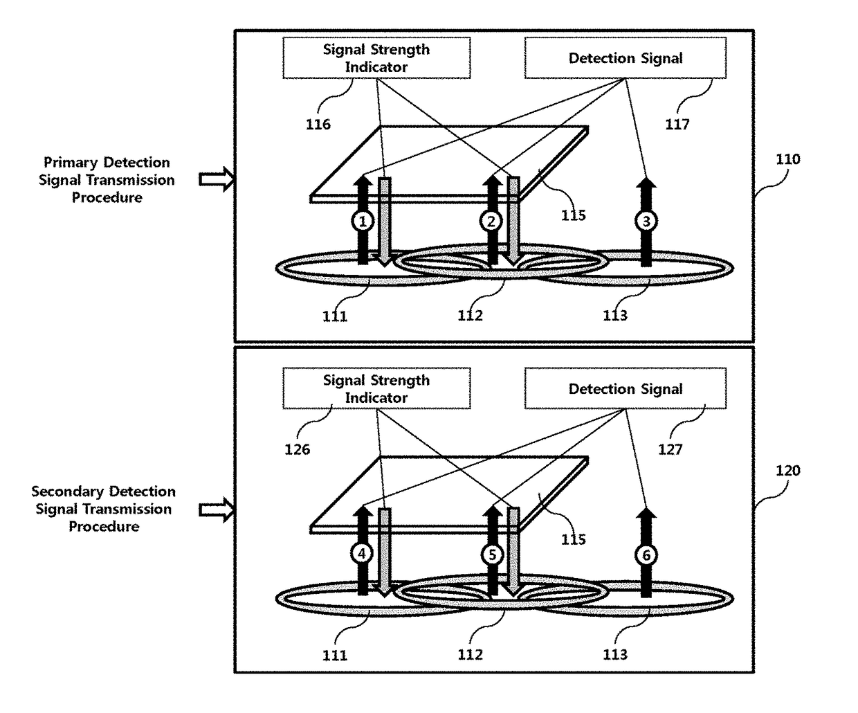
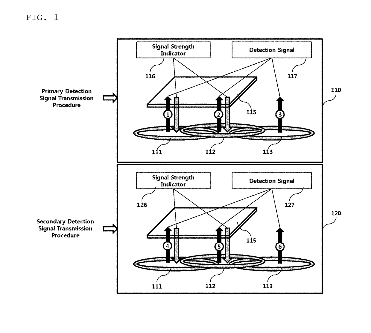
The patent provides a multi-coil wireless charging method and apparatus that have several advantages. Firstly, it improves the recognition rate for wireless power receivers and reduces the time required for recognition. Secondly, it minimizes the time required for recognition and standby power consumption by dividing the transmission coils into groups and performing a sensing procedure with the wireless power receiver. Thirdly, it optimizes the use of transmission coils and reallocates them for each wireless power transmitter based on the sensing result for the wireless power receiver. Overall, the method and apparatus facilitate wireless charging and improve the overall user experience.

Problems solved by technology

Therefore, supply of power to these devices or sensors is a new challenge.
In addition, as the kinds of portable devices such as Bluetooth handsets and music players like iPods, as well as mobile phones, rapidly increase in number, charging batteries thereof has required time and effort.
As a result, devices are generally required to be placed adjacent to a charger or a pad, which is disadvantageous.
However, the distance and space available for this scheme are limited, and the energy transfer efficiency of the scheme is rather low.
Therefore, it takes a lot of time to recognize the wireless power receiver.
Moreover, the power of the capacitor of the charged wireless power receiver is discharged through the detection signal, and thus the wireless power receiver fails to transmit a predetermined response signal including a signal strength indicator to the wireless power transmitter.
As a result, the receiver fails to be recognized.
Further, the conventional method of repeatedly transmitting the detection signal sequentially through the respective transmission coils a predetermined number of times requires large consumption of standby power.

Method used


Image

  • Multi-coil wireless charging method, and apparatus and system therefor
  • Multi-coil wireless charging method, and apparatus and system therefor
  • Multi-coil wireless charging method, and apparatus and system therefor

Examples


Embodiment Construction

[0080]Hereinafter, an apparatus and various methods to which embodiments of the present disclosure are applied will be described in detail with reference to the drawings. As used herein, the suffixes “module” and “unit” are added or used interchangeably to facilitate preparation of this specification and are not intended to suggest distinct meanings or functions.

[0081]In the description of the embodiments, it is to be understood that, when an element is described as being “on” / “over” or “beneath” / “under” another element, the two elements may directly contact each other or may be arranged with one or more intervening elements present therebetween. Also, the terms “on” / “over” or “beneath” / “under” may refer to not only an upward direction but also a downward direction with respect to one element.

[0082]For simplicity, in the description of the embodiments, “wireless power transmitter,”“wireless power transmission apparatus,”“transmission terminal,”“transmitter,”“transmission apparatus,”...


PUM


Abstract

The present invention relates to a multi-coil wireless charging method, and an apparatus and a system therefor, and a wireless power transmission system having a plurality of transmission coils, according to one embodiment of the present invention, comprises: first to n-th sub-wireless power transmitters respectively having a plurality of transmission coils and transmitting a first sensing signal; and a main control unit for identifying the sub-wireless power transmitter for transmitting a second sensing signal on the basis of whether a first signal strength indicator corresponding to the first sensing signal is received. Therefore, the present invention has an advantage of providing a multi-coil wireless charging method capable of more rapidly and correctly sensing a wireless power receiver.

Description

TECHNICAL FIELD[0001]Embodiments relate to a wireless power transmission technique, and more particularly, to a multi-coil wireless charging method for minimizing a time required for a wireless power transmitter equipped with a plurality of transmission coils to recognize a wireless power receiver, and an apparatus and system therefor.BACKGROUND ART[0002]Recently, as information and communication technology rapidly develops, a ubiquitous society based on information and communication technology is being formed.[0003]To allow information communication devices to be connected anytime and anywhere, sensors equipped with a computer chip having a communication function should be installed in all facilities. Therefore, supply of power to these devices or sensors is a new challenge. In addition, as the kinds of portable devices such as Bluetooth handsets and music players like iPods, as well as mobile phones, rapidly increase in number, charging batteries thereof has required time and effo...

Claims


Application Information

Patent Timeline
IPC IPC(8): H02J50/10H02J50/80H02J50/90H02J50/40
CPCH02J50/10H02J50/80H02J50/90H02J50/40H01F38/14H02J7/02H04B5/00H02J50/12H02J50/402
Inventor LEE, YUN BOKSON, JEONG NAM
Owner LG INNOTEK CO LTD
Why Eureka
Eureka Blog
Learn More