
Interference Reduction Techniques in Haptic Systems

a technology of haptic systems and reduction techniques, applied in the field of haptic-based systems, can solve the problems of insufficient reproduction of physical transducers, approach may produce additional audible noise, and sharp frequency changes

Inactive Publication Date: 2018-10-25
ULTRAHAPTICS IP LTD
View PDF6 Cites 49 Cited by
  • Summary
  • Abstract
  • Description
  • Claims
  • Application Information

AI Technical Summary

Benefits of technology

The patent text describes a technique for reducing interference in haptic-based systems and the potential for electromagnetic interference when ultrasonic haptic feedback equipment is co-located with other audio equipment or equipment containing audio functionality. The text also discusses the issue of attenuation of audio energy in the range 30 kHz to 300 kHz and how it can impact the haptic feedback control system. The technical effects of the patent text include the suppression and elimination of unwanted interference from ultrasonic haptic feedback arrays and the co-existence of ultrasonic haptic feedback arrays with other electronic and audio products.

Problems solved by technology

However, the simple implementation has several problems with sharp frequency changes, which are not well reproduced by the physical transducers.
Further, the approach may produce additional audible noise due to the sharp changes in frequency and effective phase.
The modulation is used to form constructive and destructive interference patterns in the audio energy emitted from the array.
Variation of these interference patterns, over short periods of time, creates haptic feedback for the user.
Audio interference may occur when ultrasonic haptic feedback equipment is co-located with other audio equipment or equipment containing audio functionality.
Electromagnetic interference may occur when ultrasonic haptic feedback equipment is co-located with other audio equipment or equipment containing audio functionality.
The recent development of ultrasonic haptic feedback equipment means existing electrical and audio equipment is susceptible to these interferences.
This can cause the output of a physical transducer to fluctuate due to differences in frequency response.
However, the seemingly obvious approach yields properties that are undesirable.
This creates an unwanted discontinuity in frequency.
Non-idealities in the implementation of the haptic array modulation scheme can create spurs in the frequency response of audio output from the array.
When the haptic array transmits interference within the audio equipment, such interference will be generated by the haptic equipment.

Method used


Image

  • Interference Reduction Techniques in Haptic Systems
  • Interference Reduction Techniques in Haptic Systems
  • Interference Reduction Techniques in Haptic Systems

Examples


Embodiment Construction

I. Continuous Phase Manipulation for Dynamic Phased-Array Systems

[0027]A. Effects of C0 Continuity in Phase

[0028]The class C0 consists of all continuous functions. The haptic system, which may include a mid-air haptic system, may be updated by continuously introducing phase and amplitude changes to each transducer. These phase and amplitude changes are generated by interpolating system states, which are representations of the state of the full set of transducers. These interpolations may generate a newly defined delay and duty cycle measured in ticks of an output clock that is ticking at some multiple greater than twice the carrier frequency. This delay and duty cycle can be interpreted as a string of binary digits with a length of this multiple in which the signal is high or 1 for some quantity of these ticks and low or 0 for the remainder.

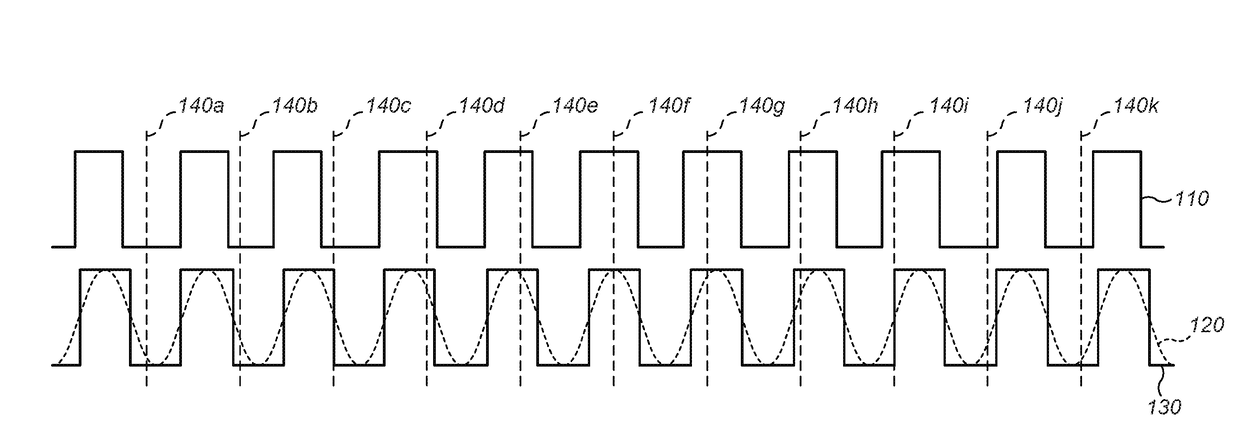
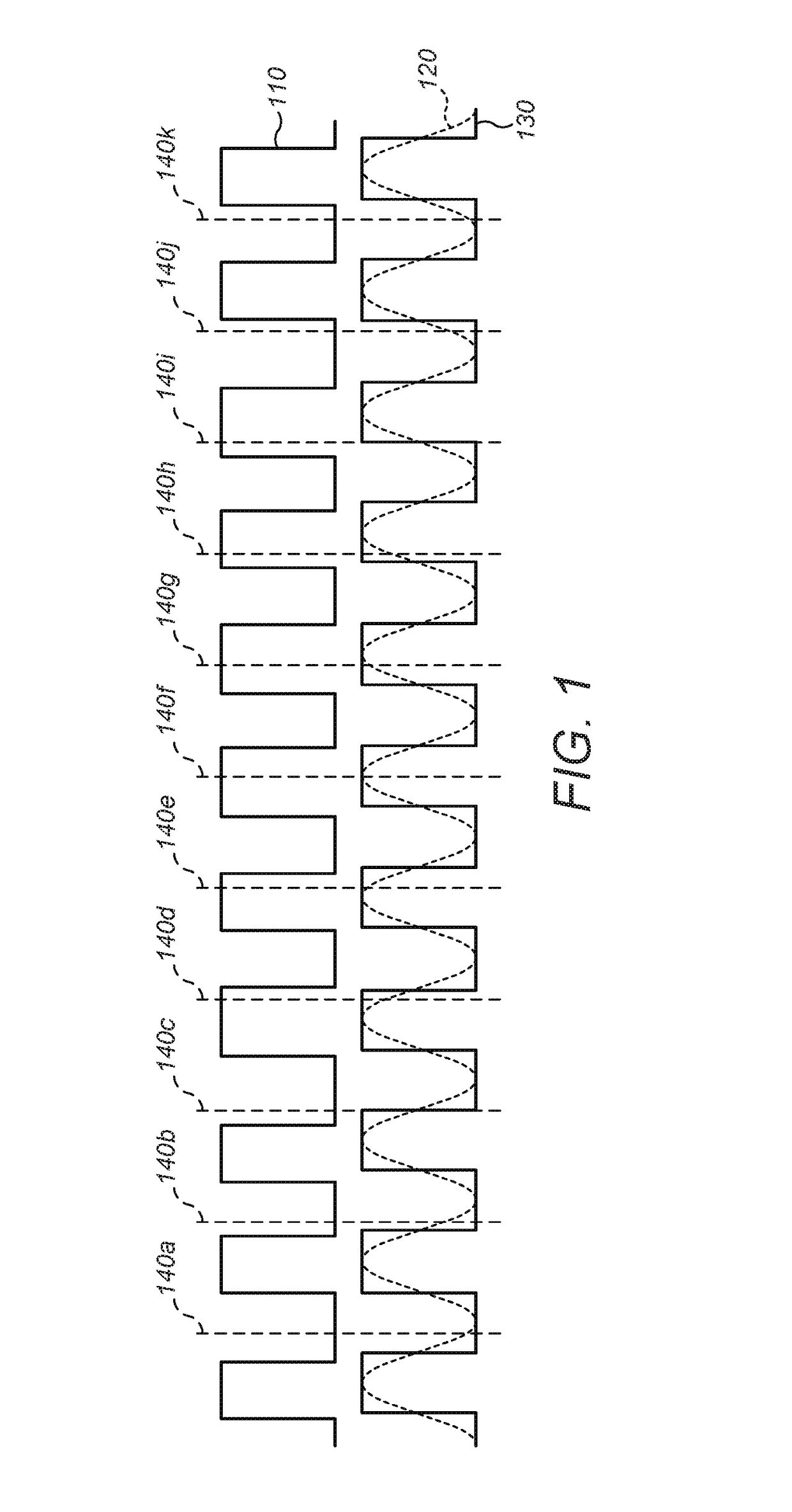
[0029]This approach is illustrated in FIG. 1 where a signal generated in this way is shown to exhibit unwanted fluctuations in duty cycle and fr...


PUM


Abstract

As control points in haptic systems move around, the phase offsets for each transducer change at discrete points in time. These are each expressed as a phase offset combined with a monochromatic carrier frequency. To prevent sharp frequency changes, an algorithm that maintains smooth transitions is used. Further, non-idealities in the implementation of haptic array modulation can create spurs in the frequency response of audio output from the array. Adjusting the signal carrier frequency and the signal modulating frequency may substantially reduce audio noise via a notch filter centered at an interpolation frequency.

Description

RELATED APPLICATIONS[0001]This application claims the benefit of the following two U.S. Provisional patent applications, all of which are incorporated by reference in their entirety:[0002]1) Ser. No. 62 / 489,161, filed on Apr. 24, 2017; and[0003]2) Ser. No. 62 / 511,397, filed on May 26, 2017.FIELD OF THE DISCLOSURE[0004]The present disclosure relates generally to interference reduction techniques in haptic-based systems.BACKGROUND[0005]A continuous distribution of sound energy, which will be referred to as an “acoustic field”, may be used for a range of applications including haptic feedback in mid-air.[0006]By defining one or more control points in space, the acoustic field can be controlled. Each point can be assigned a value equating to a desired amplitude at the control point. A physical set of transducers can then be controlled to create an acoustic field exhibiting the desired amplitude at the control points.[0007]Each transducer in the set is driven with a phase offset such tha...

Claims


Application Information

Patent Timeline
Patent Type & Authority Applications(United States)
IPC IPC(8): B06B1/16B06B1/02H04R1/28G06F3/01
CPCB06B1/166B06B1/0261H04R1/2869G06F3/016G10K11/343G10K15/02
Inventor LONG, BENJAMIN JOHN OLIVERCARTER, THOMAS ANDREWTESTER, DAVID PHILIP
Owner ULTRAHAPTICS IP LTD
Learn More