Cutting tool and cutting insert

a cutting tool and insert technology, applied in the field of cutting tools, can solve the problems of time-consuming, complicated clamping means, and complicated design of the tool holder body

Inactive Publication Date: 2018-10-25
SECO TOOLS AB
View PDF0 Cites 0 Cited by
  • Summary
  • Abstract
  • Description
  • Claims
  • Application Information

AI Technical Summary

Benefits of technology

[0003]It is desirable to provide a cutting tool in which the design and machining of the tool holder body can be simplified. It is also desirable to provide a cutting tool that can ream smaller holes than conventional reaming tools having indexable inserts, such as hole diameters less than 11.95 mm. It is also desirable to provide a cutting tool and insert that facilitate indexing or change of a worn insert.
[0016]According to another aspect of the present invention, the free end of the integral mounting portion is convexly V-shaped and forms two chamfers, each forming an internal acute angle with a plane containing the longitudinal axis of the integral mounting portion making an inclined abutment possible in order to save space.

Problems solved by technology

In either event, design of a tool holder body is complicated when it is desired to position the cutting insert so that a working cutting edge of the cutting insert defines a certain angle with a longitudinal axis of the tool holder body, and so that rake and relief surfaces of the cutting insert are properly oriented relative to the tool holder body.
Handling of clamping means is complicated and time consuming, especially for small tool diameters such as below 11.95 mm.

Method used


Image

  • Cutting tool and cutting insert
  • Cutting tool and cutting insert
  • Cutting tool and cutting insert

Examples


Embodiment Construction

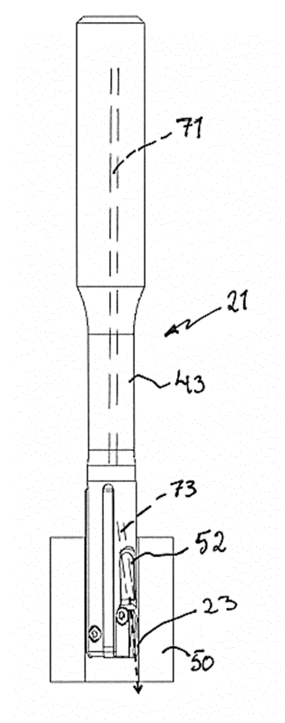
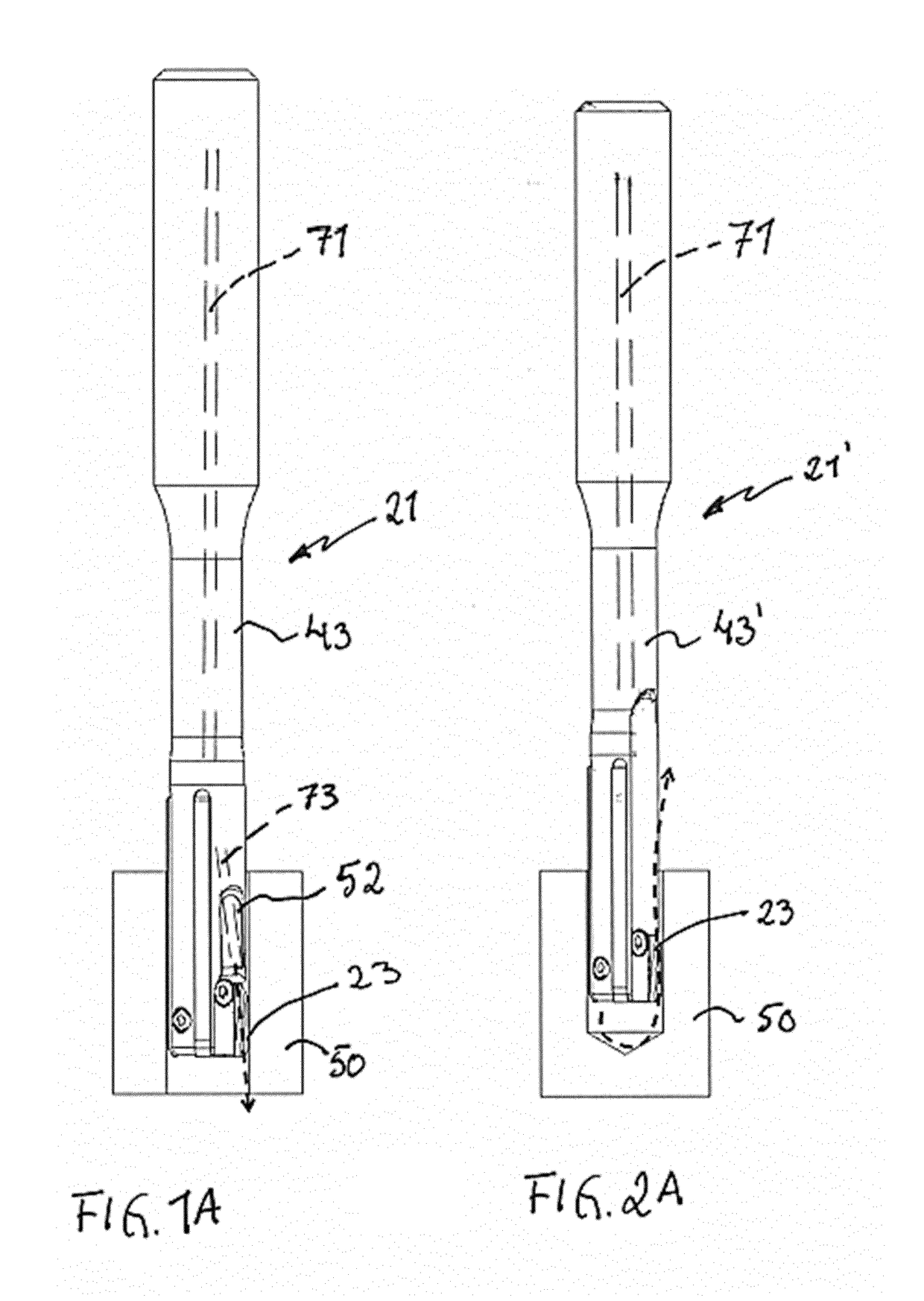
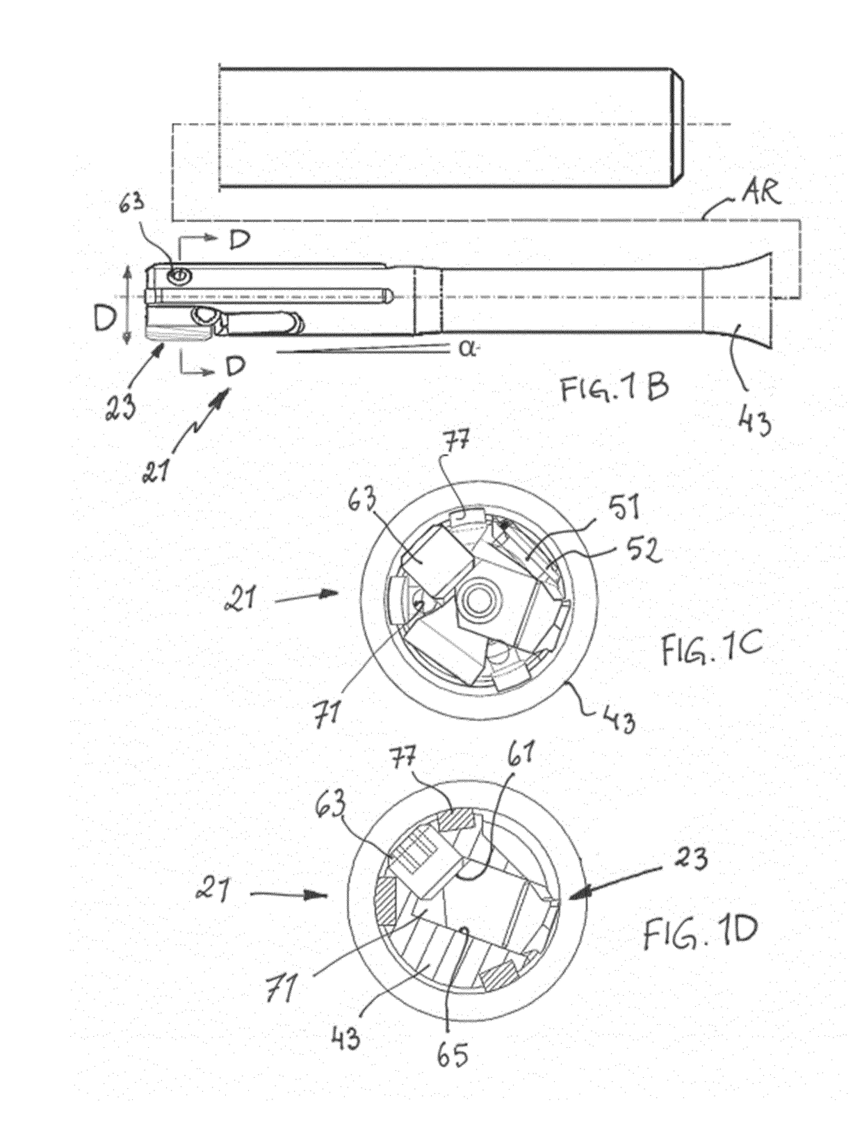
[0023]A reaming tool 21, 21′ and a cutting insert 23 according to the present invention are shown in the figures. The reaming tool 21, 21′ comprises the cutting insert 23 and a tool holder body 43, 43′. The reaming tools 21, 21′ are identical or substantially identical except for the manner in which fluid is transported in respective tool holder body.

[0024]The reaming tool 21 shown in FIGS. 1A-1D is particularly suitable to ream through-holes in a workpiece 50 and allow a fluid jet to directly flush the active cutting edge as illustrated by the dotted arrow in FIG. 1A. A body channel 71 (shown in phantom) can be provided to extend at least partially through a tool holder body 43, and a branch channel 73 (shown in phantom) can be provided in the tool holder body and exit via an opening 51 below a cover plate 52. The body channel 71 and the branch channel 73 can be in flow communication when the cutting insert 127 is mounted in the tool holder body 14 and can be used, for example, for...


PUM


Abstract

A reaming tool includes a tool holder body and at least one one-piece indexable reaming insert. The reaming insert includes more than one cutting edge. The tool holder body has an insert clamp for clamping the reaming insert relative to the tool holder body. The cutting edge extends beyond a periphery of the tool holder body when the reaming insert is clamped relative to an abutment surface of the tool holder body. The reaming insert has a head and an integral mounting portion, the tool holder body having an opening in which the integral mounting portion of the cutting insert is disposed. A reaming insert for a tool is also disclosed.

Description

BACKGROUND AND SUMMARY[0001]The present invention relates generally to cutting tools and, more particularly to reaming tools.[0002]In most cutting tools having replaceable cutting inserts, a cutting insert is mounted in an insert seat in a tool holder body and is clamped to an abutment surface by a clamping means such as a screw extending through a hole in the cutting insert into an internally threaded hole in the tool holder body or in an intermediate structure that is itself clamped to a surface formed in an insert seat formed on the tool holder body such as in WO 2008 / 121055 A1. In either event, design of a tool holder body is complicated when it is desired to position the cutting insert so that a working cutting edge of the cutting insert defines a certain angle with a longitudinal axis of the tool holder body, and so that rake and relief surfaces of the cutting insert are properly oriented relative to the tool holder body. The finished tool holder body generally has a single fu...

Claims


Application Information

Patent Timeline
Patent Type & Authority Applications(United States)
IPC IPC(8): B23D77/02B23D77/00
CPCB23D77/025B23D77/006B23C2200/161B23C2200/168B23D2277/064B23D2277/34
Inventor RIMET, LILIAN
Owner SECO TOOLS AB
Why Eureka
Try Eureka