
Method for manufacturing and repairing a composite construction turbine blade

Inactive Publication Date: 2018-10-25
SIEMENS ENERGY INC
View PDF0 Cites 4 Cited by
  • Summary
  • Abstract
  • Description
  • Claims
  • Application Information

AI Technical Summary

Benefits of technology

The patent describes a method for fabricating composite metal-ceramic or metal-metal gas turbine engine blades by mechanically joining components and holding them in a locked position using a separately formed metallic retainer member. The retainer member is formed by a sequential-layer material addition, additive manufacturing method. The invention also includes a method for repairing or retrofitting turbine blade tips with a ceramic blade tip splice component. The technical effects of the invention include improved engine efficiency, reduced weight, and enhanced durability of turbine blades.

Problems solved by technology

During engine operational service, combustion gas exposure, FOD, and blade tip rubbing can erode blade surfaces, even those constructed of superalloy materials.
However, structural repair welding processes can induce cracks in metallic blade material, especially in superalloy material.
Accordingly, it has not been practical to repair or retrofit existing metallic blade castings by adding ceramic inserts after the original blade body casting process.

Method used


Image

  • Method for manufacturing and repairing a composite construction turbine blade
  • Method for manufacturing and repairing a composite construction turbine blade
  • Method for manufacturing and repairing a composite construction turbine blade

Examples


Embodiment Construction

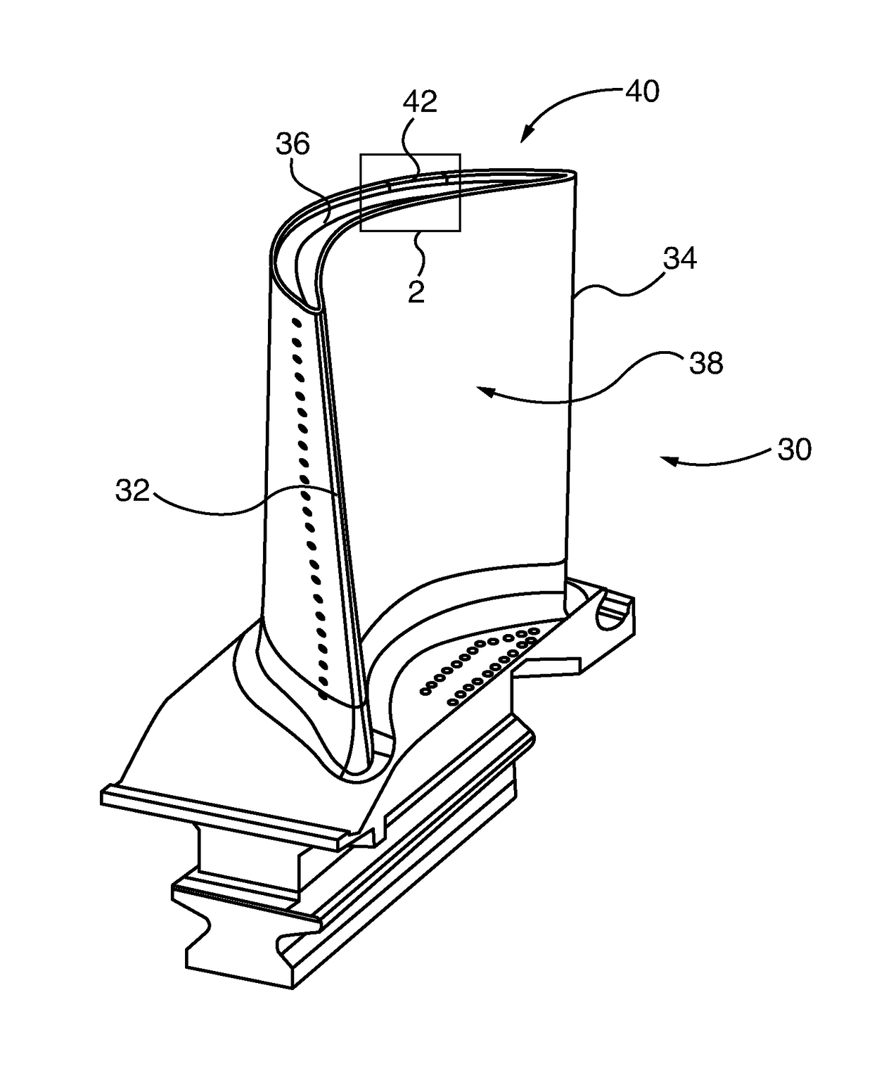
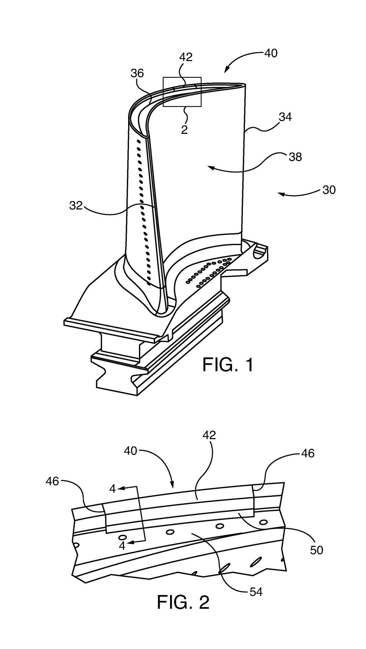
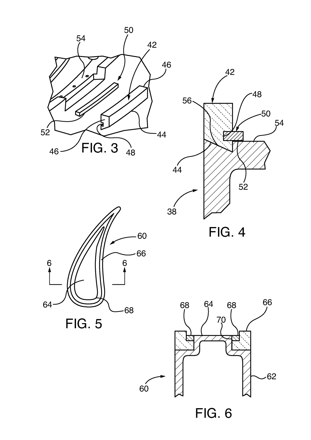
[0039]Exemplary embodiments of the invention fabricate composite turbine blades, which include a metallic blade body and one or more splice components, such as blade squealer tips or other types of blade tip, as well as leading edge inserts. In some embodiments, the metallic blade body comprises a superalloy. In some embodiments, the splice components comprise ceramic material. In other embodiments, the splice components comprise metal. The splice component mechanically interlocks with the metallic blade body by mating first and second joint portions respectively formed in the blade body and splice component. The respective mechanical joint portions are subsequently held in an interlocked position by a separately formed and applied, independent metallic retainer member. In some embodiments, the retainer member is formed by a sequential-layer material addition, additive manufacturing method. The methods are also useful for repair or retrofitting of non-composite, metallic blades end ...


PUM


Abstract

Methods for manufacture of composite construction blades (30) for gas turbine engine compressor or turbine sections. A splice component (42), such as a squealer or other blade tip (40), or leading edge (184), or repair splice mechanically interlocks with a metallic blade body (38), including a superalloy blade body. In the embodiment of FIGS. 1-4 the respective interlocking mechanical joints ramped, opposed surfaces (44, 46, and 56) are subsequently held in an interlocked position by a separately formed and applied, independent metallic retainer member (50). The retainer member (50) is external the mechanical joint portion ramped, opposed surfaces (44, 46 and 56) and is formed by a sequential-layer material addition, additive manufacturing method. The methods are also useful for repair or retrofitting of non-composite, metallic blades end caps, leading edges, or other damaged structure.

Description

PRIORITY CLAIM AND CROSS REFERENCE TO RELATED APPLICATIONS[0001]This application incorporates by reference in its entirety copending International Application entitled “COMPOSITE METALLIC AND CERAMIC GAS TURBINE ENGINE BLADE”, Docket 2015P17922WO, filed concurrently with this application, and assigned Ser. No. ______.STATEMENT REGARDING FEDERALLY SPONSORED RESEARCH[0002]Development for this invention was supported in part by Contract No. DE-FE0023955, awarded by the United States Department of Energy. Accordingly, the United States Government may have certain rights in this invention.TECHNICAL FIELD[0003]The invention relates to composite construction blades for gas turbine engine compressor or turbine sections. More particularly, the invention relates to composite construction gas turbine engine blades, where components are joined to each other by interlocking mechanical joints that are subsequently held in an interlocked position by a separately formed, and applied, independent me...

Claims


Application Information

Patent Timeline
IPC IPC(8): B23P6/00B33Y10/00B33Y80/00B22F7/06B22F5/04B22F3/00F01D5/00F01D5/28
CPCB23P6/005B33Y10/00B33Y80/00B22F7/062B22F5/04B22F3/008F01D5/005F01D5/282B22F2007/068F05D2240/303F05D2240/307F05D2300/603F05D2230/80F05D2300/175F05D2230/50B23P6/002F01D5/147F01D5/20F01D5/284F05D2260/37F05D2300/6033B22F7/08B23K2101/001Y02P10/25B22F10/28B22F10/25B22F10/14
Inventor WIEBE, DAVID J.LANDRUM, EVAN C.
Owner SIEMENS ENERGY INC
Learn More