Pressurized Beverage Dispensing System

a beverage and beverage technology, applied in the field of beverage dispensing systems, can solve the problems of increasing wasted beverage, increasing the horizontal positioning of the keg in the frame, and prone to horizontal inclination of the keg in an unpredictable fashion, so as to increase the number of beverage kegs, reduce the floor space, and maximize the effect of organization

Inactive Publication Date: 2018-10-25
WRIGHT JON
View PDF7 Cites 0 Cited by
  • Summary
  • Abstract
  • Description
  • Claims
  • Application Information

AI Technical Summary

Benefits of technology

[0009]The system and device herein, allows for the positioning of such kegs, in a horizontal disposition, rather than the conventional vertical disposition. It has been found in experimentation that positioning of beverage kegs in a horizontal disposition allows for stacking and, thus, an elevated positioning of multiple kegs in the same floor space as a single beverage keg. This has been found to maximize and organize, as well as increase the number of beverage kegs which may be stored in the same cold storage area as a single ground positioned upright keg. Such allows restaurants and bars to offer more brands of beverages or to reduce the floor space in a cooler used for beverage kegs, either of which provides significant utility to owners of such establishments.
[0013]A forming of a portion of the tubing forming the spear from a flexible tubing of a material, such as silicone, was found to solve the problem initially. However, unexpectedly, it was found in a liquid environment, the distal end of the spear formed by the flexible tube did not always settle to the lowest point of the sidewall of the keg. The addition of a flared weighted end piece to the flexible portion of the tubing forming the spear was found to provide the best mode of the device and system herein. The weighted distal end employs gravity to self-position the distal end of the tube forming the spear, substantially centered and adjacent or in contact with the lowest point of the sidewall of the horizontally placed keg. The flaring of the end of the end piece solved another problem that initially developed with a non-flared weighted end piece, in that the opening for ingress of fluid flowed better when the opening end of the flared endpiece was used. As such, in the most preferred mode of the device herein, an endpiece formed of metal, such as stainless steel, is engaged to the distal end of the flexible tube portion of the spear. Further preferred is a frustoconical shape where a wider opening provides the intake for fluid which is communicated to the flexible tube engaged opening.
[0014]As such, the system herein may be employed with just the stackable frame having a declining angle for the support surface toward the endwall of the keg opposite that hosting the coupling valve in a minimized fashion. Enhanced function is provided by inclusion of a flexible portion of the tubing forming the spear extending from the coupling valve. Optimum performance is achieved where a weighted metal end piece is engaged with the distal end of the flexible portion of the spear, especially if flared.
[0018]It is an object of the invention to provide a system for horizontally disposed stacking of beverage dispensing kegs to maximize storage in a commercial cooler.
[0019]It is an object of the invention to provide such a system, which also minimizes beverage waste, as well as maximizes the ease to which fluid conduits may be engaged with individual beverage kegs by aligning them in stacks through positioning in respective frame passages in the formed stack.

Problems solved by technology

However, during further experimentation, to increase storage in a commercial cooler and allow for more spigots at the bar from more kegs in the cooler, it was found unexpectedly that the kegs tended to angle horizontally in an unpredictable fashion over time in such a pyramid of containers stacked upon and against each other.
Further, while doable, it was found to be time consuming to replace a single empty keg at the bottom of the stack.
However, unexpectedly, it was found the horizontal positioning of the keg in the frames increased wasted beverage, as commercial projecting tubes or spears are configured for ingress of the beverage adjacent to an opposing endwall through a closely placed distal end of the projecting tube forming the spear.
Because the extension of the spear from the coupling valve is dependent on a number of variables, such as varying tightening by different users, during experimentation it was found that the curved spear tube did not always end up in the correct position even when a direction was marked.

Method used


Image

  • Pressurized Beverage Dispensing System
  • Pressurized Beverage Dispensing System
  • Pressurized Beverage Dispensing System

Examples


Embodiment Construction

[0029]In this description, the directional prepositions of up, upwardly, down, downwardly, front, back, top, upper, bottom, lower, left, right and other such terms refer to the device as it is oriented and appears in the drawings and are used for convenience only; they are not intended to be limiting or to imply that the device has to be used or positioned in any particular orientation.

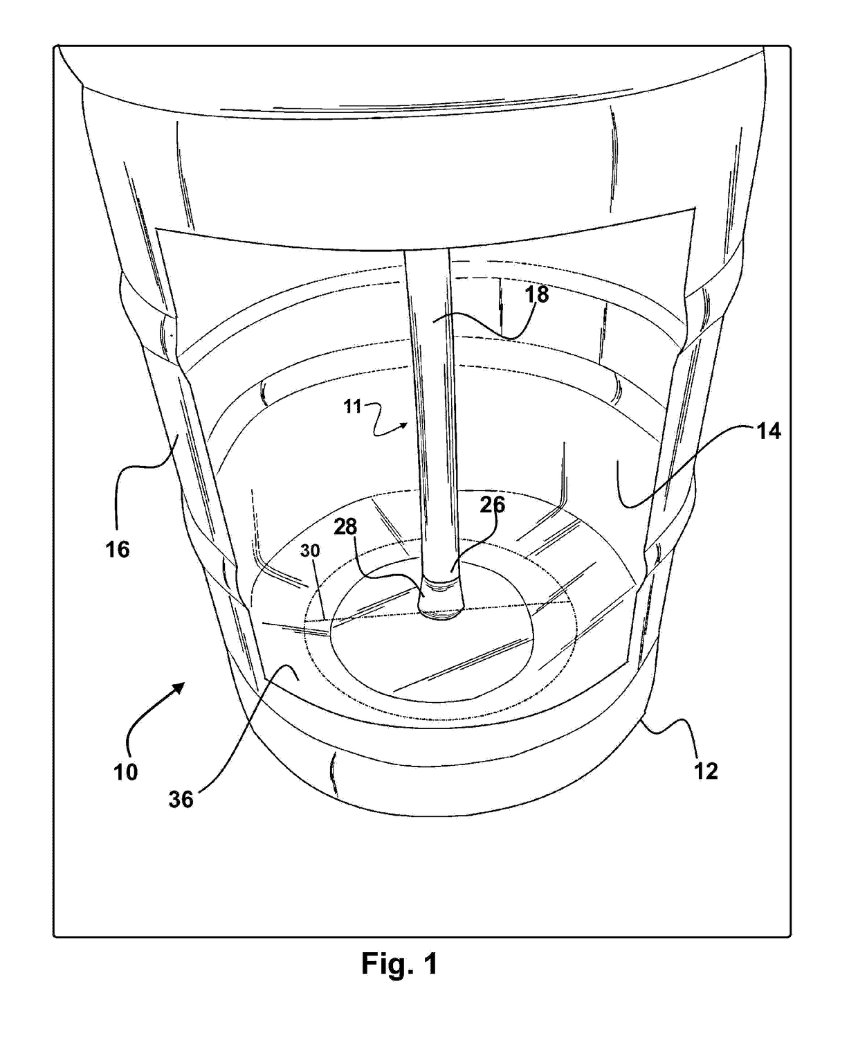
[0030]Now referring to drawings in FIGS. 1-6, wherein similar components are identified by like reference numerals, the device 10 as shown in FIG. 1, depicts an overhead perspective view of a conventional beverage keg 12 in the conventional vertical disposition used widely to dispense beverages from the internal cavity 14 of the beverage keg 12. As shown, a portion of the sidewall 16 is removed, to reveal components of the device 10 herein, which form a spear 11 adapted for positioning within the internal cavity 14 of a beverage keg 12. In a conventional beverage keg 12, the spear 11 is well known to ...


PUM


Abstract

A keg positioning system is provided having a flexible portion of an internal spear for beverages dispensed from the internal cavity of a beverage keg. The flexible portion enables use of the keg in both a vertical or horizontal orientations, with minimal waste of the beverage. A frame may also be employed to provide for vertical stacking of multiple kegs above a support floor space sized for the lowest frame in the stack.

Description

[0001]This application claims priority to U.S. Provisional Patent Application Ser. No. 62 / 488559, filed on Apr. 21, 2017, which is incorporated herein in its entirety by this reference thereto.FIELD OF THE INVENTION[0002]The present invention relates to the dispensing of beverages from containers under pressure. More particularly, it relates to a metal container configuration for containers of beverages which are fermented and then shipped in the metal container. The system allows for dispensing the liquid beverage, in both a horizontal and vertical storage position, with a complete emptying of the beverage from the container in either position. In other modes, stacking of the container is provided to save cold storage space and allow for beverage selling establishments to increase the number of different beverages which may be dispensed from containers using the same or a smaller cold storage area.PRIOR ART[0003]For beer and ale served in bars and restaurants, breweries conventiona...

Claims


Application Information

Patent Timeline
Patent Type & Authority Applications(United States)
IPC IPC(8): B65D21/02B67D1/08
CPCB65D21/0215B65D21/0237B67D1/0802B67D1/0892B67D2001/0825B67D2210/00031
Inventor WRIGHT, JON
Owner WRIGHT JON
Why Eureka
Try Eureka