
Load-based tire inflation system for heavy-duty vehicles

a tire inflation system and tire technology, applied in the direction of heavy duty tires, vehicle maintenance, transportation and packaging, etc., can solve the problems of tire pressure not being checked, difficulty in manually checking and maintaining the optimal tire pressure for each and every tire, and air leakage from tires, etc., to increase and decrease fluid pressure

Active Publication Date: 2018-11-01
HENDRICKSON USA L L C
View PDF3 Cites 12 Cited by
  • Summary
  • Abstract
  • Description
  • Claims
  • Application Information

AI Technical Summary

Benefits of technology

The disclosed patent text is about an improved tire inflation system for heavy-duty vehicles. The system uses sensors to detect changes in the vehicle load and automatically adjusts the tire pressure to maintain a target pressure. This system does not require expensive or unreliable processors and can operate without them. The system can detect changes in air pressure in the suspension structures and in the tires, and make the necessary adjustments to maintain the target pressure. Overall, this load-based tire inflation system provides a more efficient and effective way to inflate tires on heavy-duty vehicles.

Problems solved by technology

However, it is well known that air may leak from a tire, typically in a gradual manner, but sometimes rapidly if there is a problem with the tire.
Such problems may be caused by deficiencies of the tire or damage caused by a road hazard.
The large number of tires on any given heavy-duty vehicle configuration makes it difficult to manually check and maintain the optimal tire pressure for each and every tire.
This difficulty is compounded by the fact that heavy-duty vehicles in a fleet may be located at a site for an extended period of time, during which the tire pressure might not be checked.
Any one of these heavy-duty vehicles might be placed into service at a moment's notice, leading to the possibility of operation with under-inflated tires.
Such operation may increase the chance of failure of a tire as compared to tires within a target pressure inflation range.
Under-inflated tires may cause excessive heat buildup within the tire causing damage to the internal structure.
Under-inflation may also increase tire wear and reduce fuel economy by about 1 to 1.5% for every 10% below the target pressure.
Development of a leak or under-inflation may cause failure of the tire if the leak continues unabated as the heavy-duty vehicle travels over-the-road.
Potential for tire failure is more pronounced in heavy-duty vehicles such as tractor-trailers that travel for long distances and / or extended periods of time.
Heavy-duty vehicles in violation are removed from service until repaired and may not be allowed to drive to a service center for repair or proper inflation.
Thus a violation may require a roadside service call, resulting in increased expense and downtime of the heavy-duty vehicle.
Over-inflation of tires may adversely affect tire performance and service life.
Over-inflation may cause tires to be more prone to puncture or damage by sudden impact, potentially causing catastrophic failure.
Over-inflation typically reduces tire surface area contacting a road surface resulting in the load carried by the heavy-duty vehicle tire being distributed over a smaller area of tire tread.
This may cause increased and / or irregular wear of the tire and decreased maneuverability and traction.
Such prior art systems rely on electronic controls, including electronic processors, to execute relatively complex algorithms to perform calculations that estimate vehicle mass.
The electronic controls generally require the use of, and may affect the operation of, the heavy-duty vehicle electrical system.
While satisfactory for their intended functions, prior art tire inflation systems are limited in certain situations.
However, due to varying weights of heavy-duty vehicle loads, many potential values for target inflation pressures exist.
Manual adjustment of the target inflation pressure of known systems is also impractical or inconvenient for the vehicle operator due to the varying weight of heavy-duty vehicle loads.
Electronic controls of known systems are undesirably expensive, complex, difficult to install and configure, and potentially unreliable.

Method used


Image

  • Load-based tire inflation system for heavy-duty vehicles
  • Load-based tire inflation system for heavy-duty vehicles
  • Load-based tire inflation system for heavy-duty vehicles

Examples


Embodiment Construction

[0023]For exemplary purposes, details are set forth in order to provide an understanding of the disclosed subject matter. It will be understood, however, that the disclosed subject matter can be practiced and implemented without these specific details.

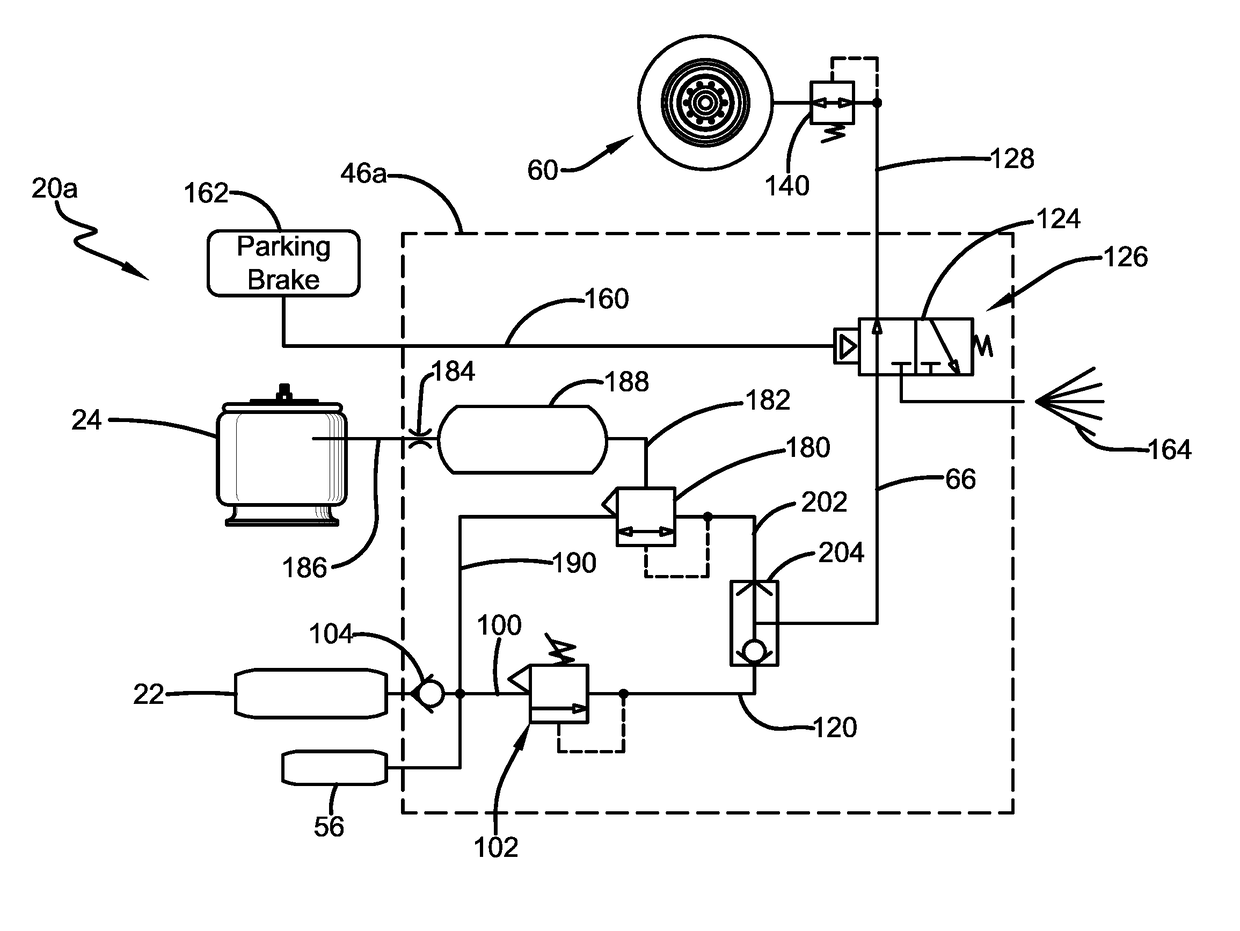
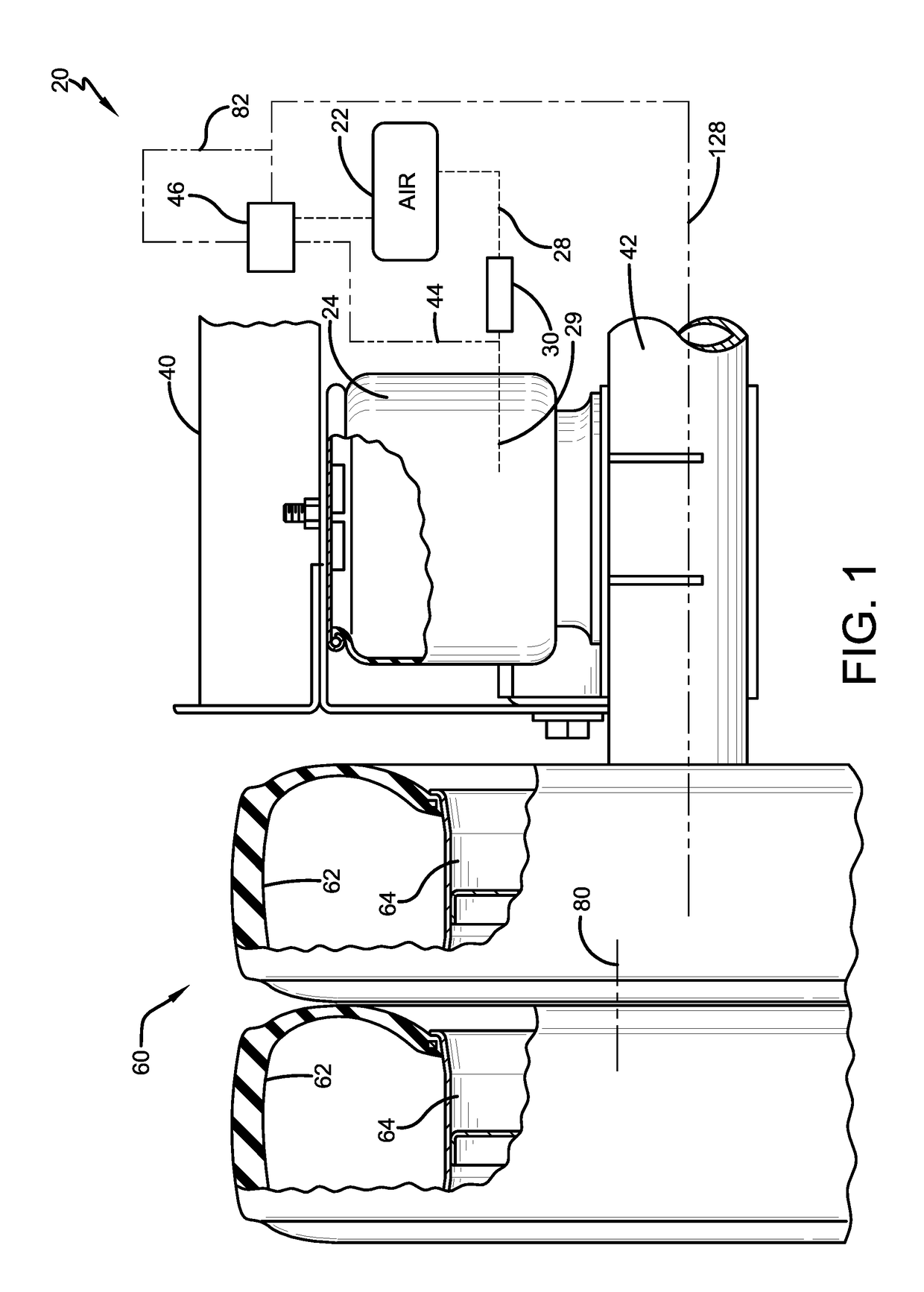
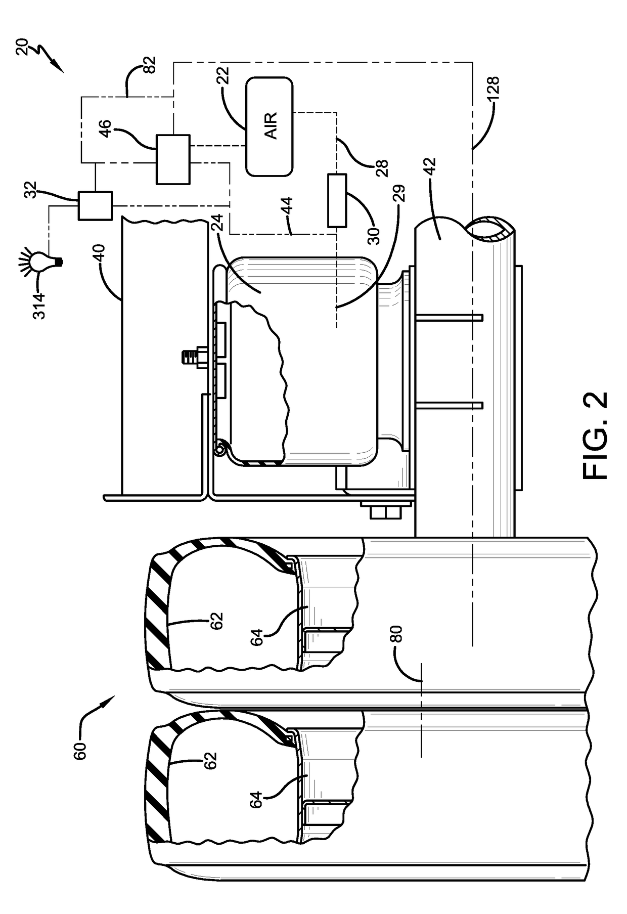
[0024]A load-based tire inflation system 20 (FIG. 1) according to one aspect, is described generally and is for use on a heavy-duty vehicle (not shown). The load-based tire inflation system 20 continuously monitors the load of the heavy-duty vehicle and automatically and continually adjusts fluid pressure in tires of the heavy-duty vehicle based on the load or total weight of the heavy-duty vehicle. This continuous and automatic pressure adjustment in the tires optimizes the pressure for a given load condition. This type of adjustment improves fuel economy of the heavy-duty vehicle and performance and service life of the tires and reduces equipment downtime and maintenance. As a result, the operating cost of the heavy-duty vehicle is d...


PUM


Abstract

A load-based tire inflation system for a heavy-duty vehicle comprises at least one source of fluid pressure, suspension structure of the heavy-duty vehicle, a tire and wheel assembly and a system to control fluid pressure in the tire and wheel assembly. The suspension structure is located between a frame member and an axle and has a condition indicative of a weight of the heavy-duty vehicle. The tire and wheel assembly is operatively mounted to the axle and is in fluid communication with the source of fluid pressure. The control system controls fluid pressure in the tire and wheel assembly in response to the condition of the suspension structure.

Description

CROSS-REFERENCE TO RELATED APPLICATION[0001]This application claims the benefit of U.S. Provisional Patent Application Ser. No. 62 / 491,319 filed Apr. 28, 2017.BACKGROUNDTechnical Field[0002]The disclosed subject matter relates generally to vehicle tire inflation systems. The disclosed subject matter relates particularly to tire inflation systems for heavy-duty vehicles that can continuously adjust fluid pressure in vehicle tires in response to load.Background Art[0003]The use of tire inflation systems in heavy-duty vehicles is well known. Many heavy-duty vehicles may include at least one trailer, and sometimes two or three trailers. As used herein, the term heavy-duty vehicle generally includes trucks, tractor-trailers or semi-trailers, and trailers. Each such heavy-duty vehicle typically includes multiple tires requiring inflation with air to target pressures for optimal performance. However, it is well known that air may leak from a tire, typically in a gradual manner, but sometim...

Claims


Application Information

Patent Timeline
Patent Type & Authority Applications(United States)
IPC IPC(8): B60C23/00B60G17/04B60S5/04
CPCB60C23/002B60G17/04B60S5/046B60G2300/042B60G2202/152B60G2300/026B60C2200/06B60G11/27B60G17/052B60G2400/252B60G2400/30B60G2400/51222B60G2400/52B60G2400/60B60C23/00336B60C23/00372B60C23/00354B60C23/0408B60G17/0155B60G2800/984
Inventor WILSON, MATT J.CERVANTEZ, JESSE W.ZAWACKI, JEFF R.
Owner HENDRICKSON USA L L C
Learn More