Target geometry for small spot x-ray tube

Active Publication Date: 2018-11-01
THERMO SCI PORTABLE ANALYTICAL INSTR
View PDF0 Cites 1 Cited by
  • Summary
  • Abstract
  • Description
  • Claims
  • Application Information

AI Technical Summary

Benefits of technology

This patent describes an X-ray tube design that includes a concave rod positioned in the outer cylinder of the tube. This concave geometry helps to position the target surface with a focal spot size of the electron beam from the emission orifice in the range of about 2-6 μm. The angle of the electron gun is set between about 10° and 45°, and the angle of the target surface is set between about 45° and 85°. The target may be made of materials such as molybdenum, rhodium, and tungsten, and the rod may be made of materials such as copper, graphite, and molybdenum. The target surface is positioned about 0.3 15 mm from the window and the focal spot size includes a diameter of about 6 μm. The patent is not limited to the specific embodiments and can be combined in different ways to achieve the same goal.

Problems solved by technology

This type of configuration produces excessive amounts of heat that limits the amount of power that can be used.
As those skilled in the art appreciate, large differences in voltage potential of objects located in close proximity to one another can often result in arcing problems.
For example, the thermal transfer capacity of a target anode structure is limited by the cross-sectional area, where a large anode cross section carries more heat but can compromise voltage standoff distance from other objects such as an electron gun.
This is a very simple and cost effective solution, but has limitations as to the considerations described above.
This helps to overcome the configuration problem of the straight rod, but makes the angles of intersection with the electron beam difficult.
For example, the stepped down configuration lengthens the electron path between the electron gun cathode and the target anode surface making focusing the x-ray emissions a challenge.
Additionally, the sharp transitions in cross-section create high voltage stress points that reduce the voltage standoff in the tube and affect the characteristics of the electric field.

Method used


Image

  • Target geometry for small spot x-ray tube
  • Target geometry for small spot x-ray tube
  • Target geometry for small spot x-ray tube

Examples


Embodiment Construction

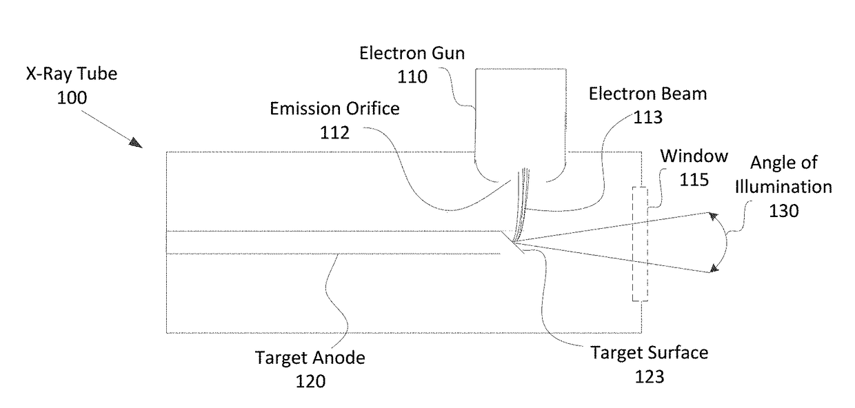
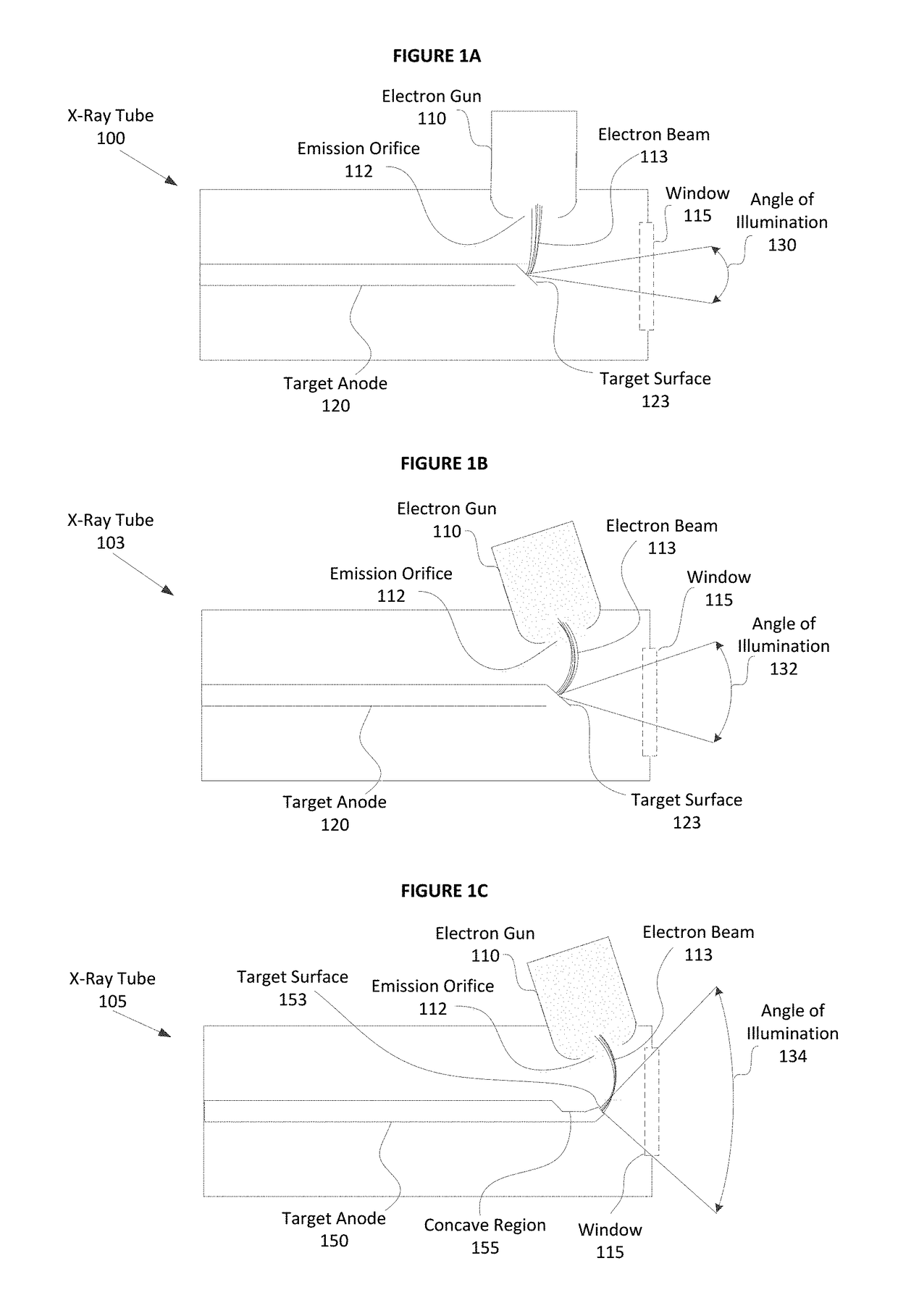
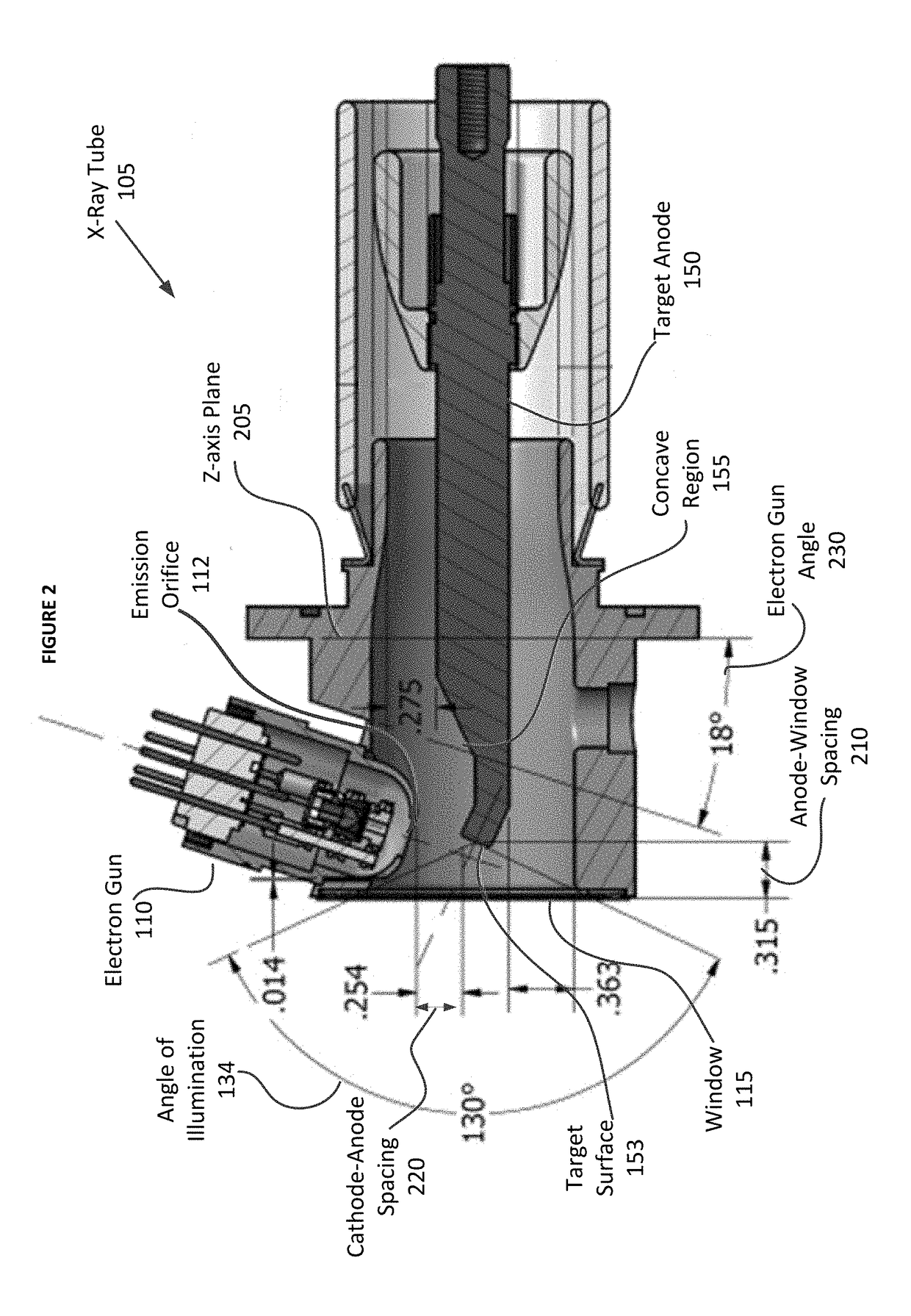
[0024]As will be described in greater detail below, embodiments of the described invention include an x-ray tube configured with a target anode positioned to have a target surface with a very small focal spot, produce a large angle of illumination, and efficiently dissipate heat generated at the target surface. More specifically, embodiments of the target anode comprise geometry with a “smoothed” transition from a central region where the structure has a large cross section to the target surface which has a relatively small cross section. The geometry also includes a curvature that enables a significantly minimized distance between 1) an electron gun type of cathode to target face, and 2) a window of the x-ray tube to the target surface which provides the large angle of illumination.

[0025]Some or all of the embodiments described herein may include one or more elements for operational control of an x-ray tube. For example, embodiments may include one or more processor or controller e...


PUM


Abstract

An embodiment of an X-ray tube is described that comprises an outer cylinder; a window positioned on an end of the outer cylinder; an electron gun comprising an emission orifice, wherein the electron gun is coupled to a side of the outer cylinder at an angle that orients the emission orifice toward the window; and a rod centrally positioned within the outer cylinder, wherein the rod comprises a concave geometry at a distal end proximal to the electron gun and a target surface configured at an angle that orients the target surface towards the emission orifice, wherein the concave geometry is configured to position the target surface to have a focal spot size of an electron beam from the emission orifice in range of about 2-6 μm.

Description

CROSS-REFERENCE TO RELATED APPLICATION[0001]This application claims the benefit of U.S. provisional patent application No. 62 / 491,606, filed Apr. 28, 2017. The contents of this application are incorporated by reference in their entirety.FIELD OF THE INVENTION[0002]The presently described invention relates generally to the field of x-ray Tube Technology. More specifically, the invention pertains to a new configuration for an x-ray tube designed to produce a very small x-ray spot with a large angle of illumination while at the same time efficiently dissipating heat from the target.BACKGROUND OF THE INVENTION[0003]X-ray tube technology is well known and some embodiments include a vacuum tube configured with a cathode that emits electrons that collide with an anode “target” to produce x-ray emissions. Those of ordinary skill in the art appreciate that x-ray emissions are used for a variety of applications that typically include directing the x-rays at a sample and measuring a response. ...

Claims


Application Information

Patent Timeline
IPC IPC(8): H01J35/08H01J35/18
CPCH01J35/08H01J35/18H01J2235/086H01J35/112
Inventor ENGLISH, II, WILLIAM FERNEAU
Owner THERMO SCI PORTABLE ANALYTICAL INSTR
Why Eureka
Try Eureka