Unlock instant, AI-driven research and patent intelligence for your innovation.
Single beam dynamic focusing method
What is Al technical title?
Al technical title is built by PatSnap Al team. It summarizes the technical point description of the patent document.
A dynamic focusing and single-beam technology, applied in optics, optical components, instruments, etc., can solve problems such as limited extraction efficiency and reduced device output capacity, and achieve the effects of high degree of realizability, easy operation, and multiple functions
Active Publication Date: 2016-05-18
LASER FUSION RES CENT CHINA ACAD OF ENG PHYSICS
View PDF2 Cites 5 Cited by
Summary
Abstract
Description
Claims
Application Information
AI Technical Summary
This helps you quickly interpret patents by identifying the three key elements:
Problems solved by technology
Method used
Benefits of technology
Problems solved by technology
In addition, the dynamic focusing of the beam is formed by the splicing of short sub-pulses in time, and the energy extraction efficiency of the device amplifier in a unit time is limited, and the amplification of short pulses will greatly reduce the output capability of the device
Method used
Image
Click on the blue label to locate the original text in one second.
Reading with bidirectional positioning of images and text.
Examples
Embodiment 1
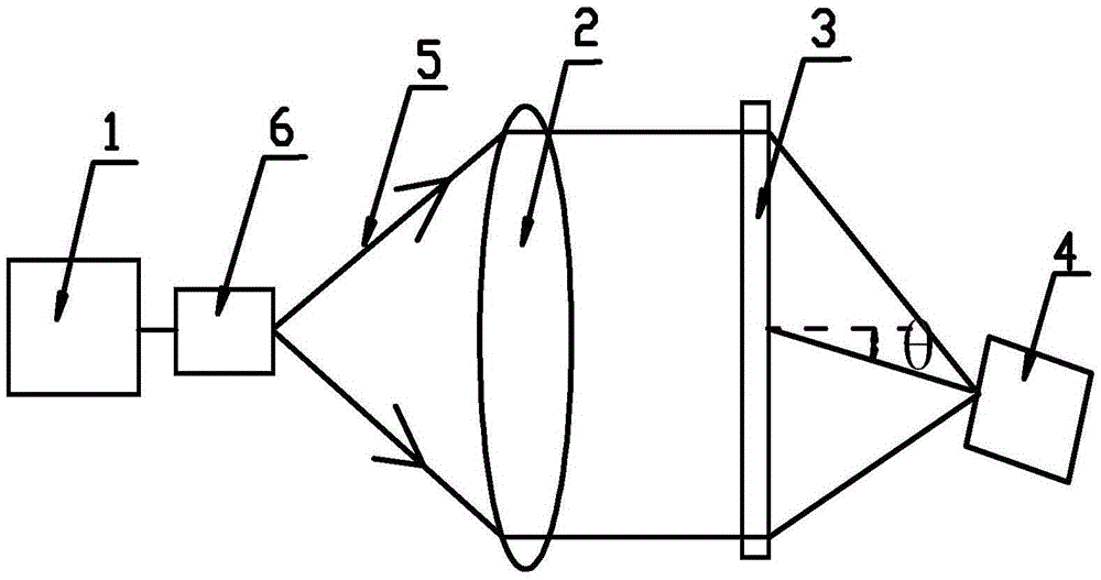
[0037] like figure 1 As shown, a single-beam dynamic focusing method includes emitting a laser pulse 5 from a laser source 1, and the laser pulse 5 is expanded into parallel light through a lens 2, and the parallel light is focused on a target pill through a holographic grating 3 to realize dynamic focusing In the process, the laser source 1, lens 2 and holographic grating 3 are arranged in a coaxial structure, and single-beam dynamic focusing is adopted, which avoids the problem of precise time control of each sub-pulse by dynamic focusing of beams, is easy to operate, and can achieve a high degree of optimization. High, and at the same time, the laser pulse 5 is not spliced by sub-pulses, and there is no problem of short pulse amplification and saturation reducing the output capability of the laser system.
[0038] The wavelength of the laser pulse 5 is increasing, the wavelength of the laser pulse 5 is λ, and the λ is determined by λ 1 increase to λ 2 , and 0.5nm≤λ 2 -...
Embodiment 2
[0053] In this embodiment, the same parts as those in Embodiment 1 will not be repeated, but the difference is:
[0054] In this embodiment, in order to match the compression change process of the target capsule, the design size of the focal spot at the target capsule is required to be reduced from 415.796 μm to 226.461 μm, and the focal spot is reduced by 45.5%.
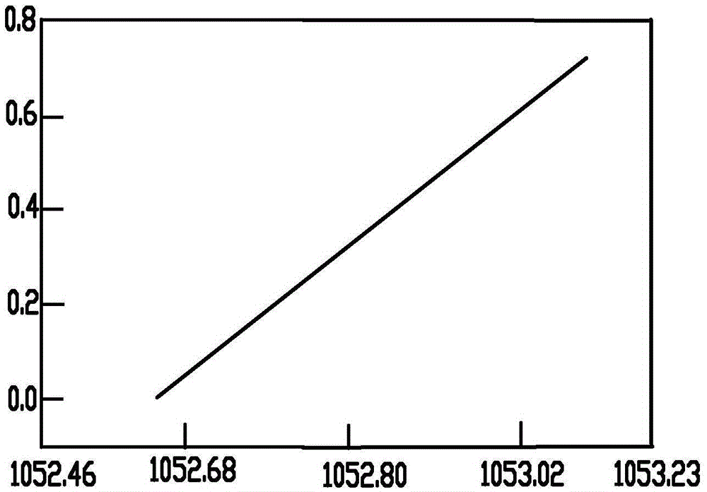
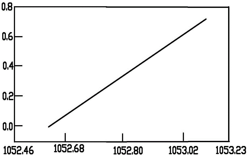
[0055] The beam aperture of the laser pulse 5 is 36mm × 36mm, the size of the holographic grating 3 is 40mm × 40mm, and its effective light aperture D=45.664mm, which adopts λ 0 =1053nm laser pulse 5 is recorded, according to geometric optics and beam aperture of laser pulse 5, beam spatial arrangement factor, preferred f 0 = 400mm.
[0056] Depend on get λ 1 =1052.462nm,λ 2 =1053.23nm, the compression change time of the target pellet is 3ns, then the phase modulation frequency of the phase modulator is 0.256nm / ns, then the wavelength of the laser pulse 5 increases from 1052.462nm to the required time of 1053.2...
PUM
Abstract
The invention relates to a single beam dynamic focusing method and belongs to the technical field of a laser device. A laser source emits a laser pulse which is focused on a pellet through a holographic grating. The wavelength of the laser pulse shows an increasing trend, and the variation range of the wavelength matches the focal spot size during a pellet compression variation process. The focusing, color separation and dynamic focusing functions on the laser pulse are realized simultaneously through the holographic grating. The single beam dynamic focusing method needs few optical elements and implements many functions. Compared with a traditional beam combination dynamic focusing method, the single beam dynamic focusing method generates more focal spots with different sizes. The variation process of the focal spots further matches the pellet compression variation process. The single beam dynamic focusing method has the characteristics of easy operation and high achievable degree, and does not have the problem that the amplification and saturation of short pulses reduce the output capacity of a laser system.
Description
technical field [0001] The invention belongs to the technical field of laser equipment, and in particular relates to a single beam dynamic focusing method. Background technique [0002] In the direct drive mode of laser inertial confinement fusion, the laser is directly irradiated on the target capsule, and the target capsule is continuously compressed and becomes smaller during the implosion process. The initial focal spot formed by the laser beam no longer matches the compressed target capsule, and the energy Drain from the edge of the ball. Furthermore, in direct drive, the cross-overlapping of focal spots on the capsule excites the ion acoustic waves, so that the beam energy is ion-acoustically transferred from the current beam to the adjacent beam, breaking the implosion symmetry. [0003] In general, different target designs have different requirements for the focal spot size. For example, the diameter of the target pellet used by the NIF device (National Ignition Fa...
Claims
Application Information
Patent Timeline
Application Date:The date an application was filed.
Publication Date:The date a patent or application was officially published.
First Publication Date:The earliest publication date of a patent with the same application number.
Issue Date:Publication date of the patent grant document.
PCT Entry Date:The Entry date of PCT National Phase.
Estimated Expiry Date:The statutory expiry date of a patent right according to the Patent Law, and it is the longest term of protection that the patent right can achieve without the termination of the patent right due to other reasons(Term extension factor has been taken into account ).
Invalid Date:Actual expiry date is based on effective date or publication date of legal transaction data of invalid patent.
Patent Type & Authority Applications(China)
IPC IPC(8): G02B27/09
CPCG02B27/0944G02B27/0955
Inventor 黄小霞袁强胡东霞
Owner LASER FUSION RES CENT CHINA ACAD OF ENG PHYSICS

