Deep channel cathode assembly

a cathode assembly and deep channel technology, applied in the field of xray tubes, can solve the problems of affecting the manufacturing cost, degrading the yield of the manufacturing process, and not easy to achieve the focal spot size below the nominal value, and achieve the effect of small focal spot generation

Active Publication Date: 2016-12-08
GENERAL ELECTRIC CO
View PDF3 Cites 4 Cited by
  • Summary
  • Abstract
  • Description
  • Claims
  • Application Information

AI Technical Summary

Benefits of technology

[0006]One advantage with the disclosed improved cathode assembly is that it provides a deep channel for holding filament that enables generation of small focal spots. The cathode assembly includes at least one deep channel and a filament arranged in each deep channel. The deep channel is configured in a cathode cup surface of the cathode assembly. The filament is arranged in the deep channels for enabling emission of electron beams from the cathode assembly.

Problems solved by technology

Therefore it is not easy to achieve focal spot size below 0.3 nominal.
The focal spot size is also very sensitive to filament set height which affects the manufacturing cost and degrades the yield of the manufacturing process.
Any change in the radius can lead to a more costly cathode production and / or focal spot size failures during operation.
Present methodologies of producing small focal spots require presence of external magnetic or biasing electric fields and / or variation in the filament coil diameter which affects the manufacturing cost.

Method used


Image

  • Deep channel cathode assembly
  • Deep channel cathode assembly
  • Deep channel cathode assembly

Examples


Embodiment Construction

[0015]In the following detailed description, reference is made to the accompanying drawings that form a part hereof, and in which is shown by way of illustration specific embodiments that may be practiced. These embodiments are described in sufficient detail to enable those skilled in the art to practice the embodiments, and it is to be understood that other embodiments may be utilized and that logical, mechanical and other changes may be made without departing from the scope of the embodiments. The following detailed description is, therefore, not to be taken as limiting the scope of the invention.

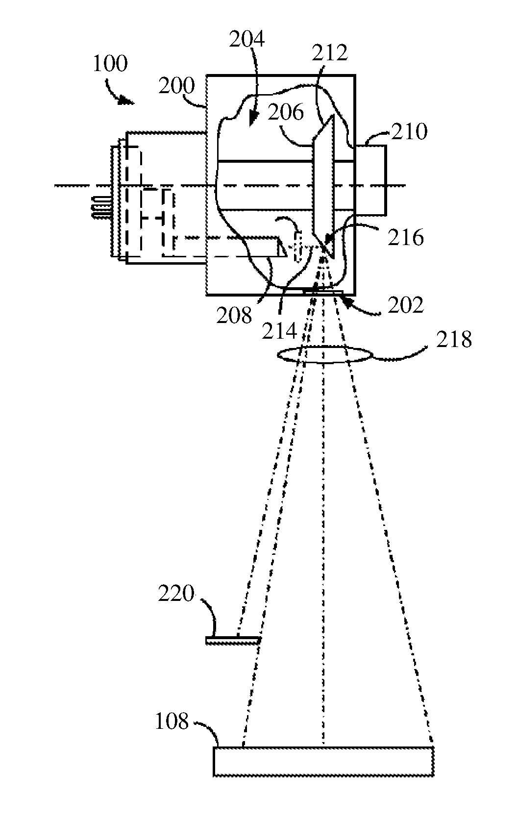
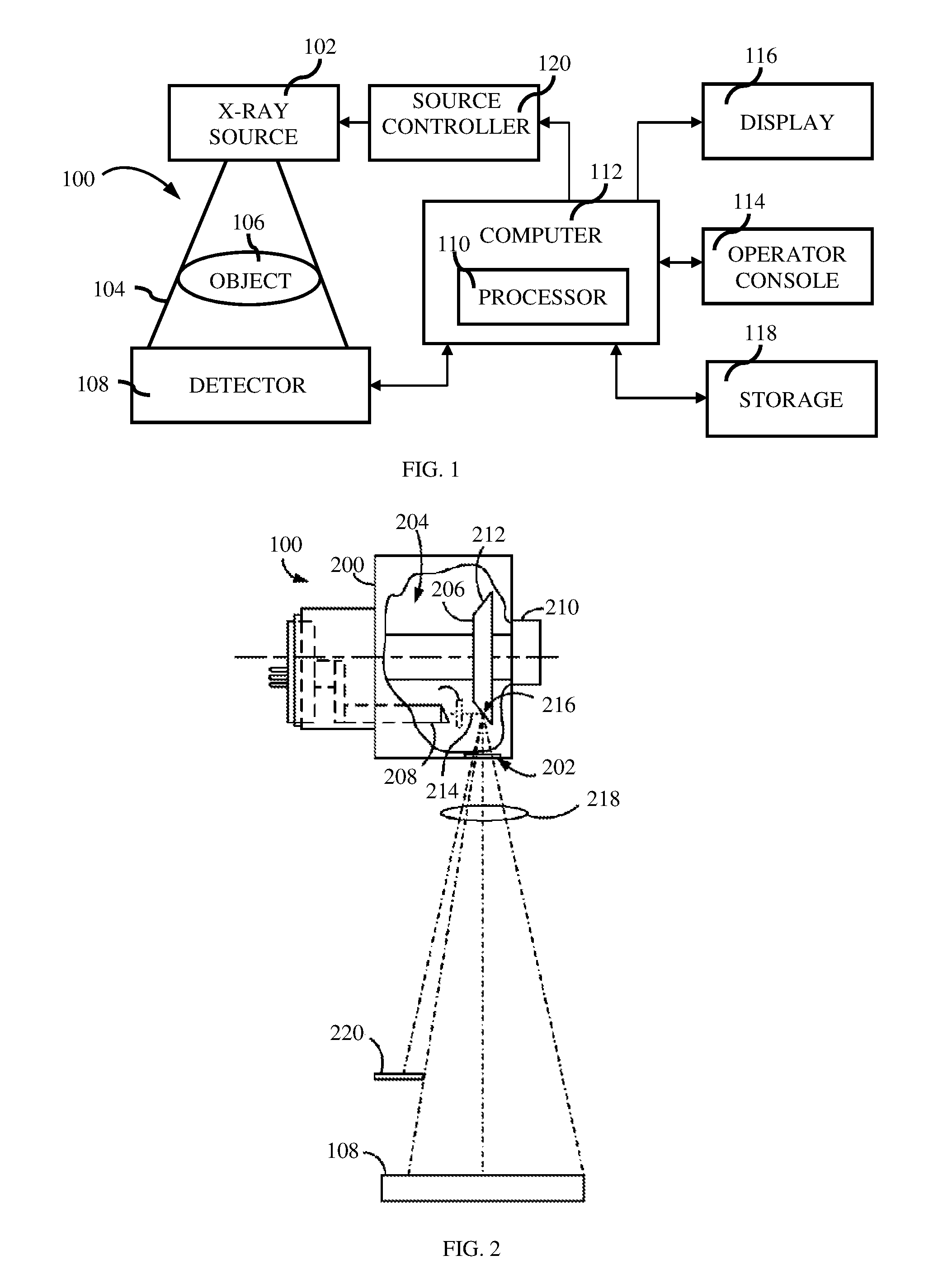
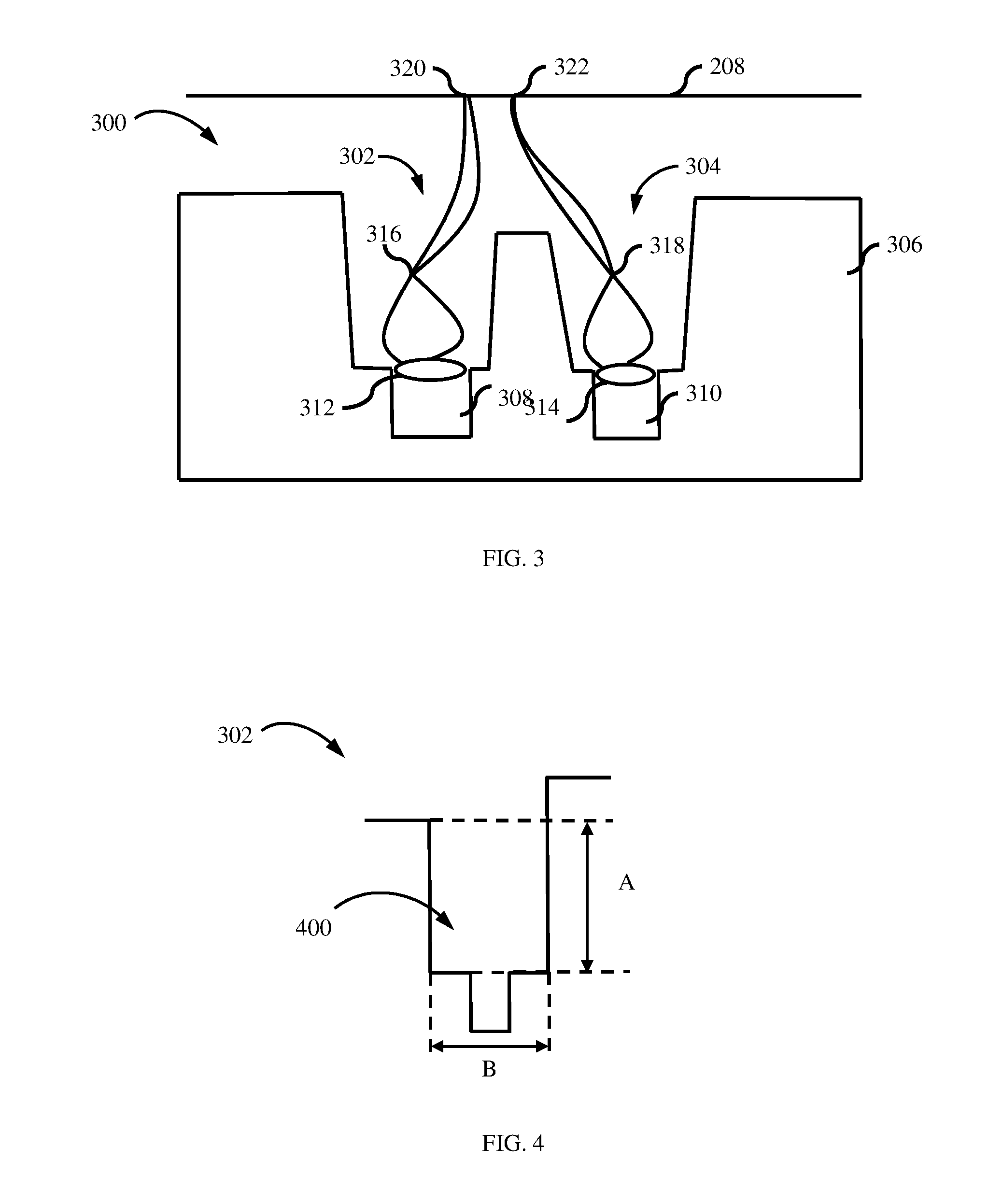
[0016]As discussed in detail below, embodiments of an improved cathode assembly is disclosed. The improved cathode assembly provides a deep channel for holding filament that enables generation of small focal spots. The cathode assembly includes at least one deep channel and a filament arranged in a deep channel. The deep channel is configured in a cathode cup surface of the cathode assemb...


PUM


Abstract

An improved cathode assembly is disclosed. The improved cathode assembly provides a deep channel for holding filament that enables generation of small focal spots, but is not limited in achieving larger focal spot sizes. The cathode assembly includes at least one deep channel and a filament arranged in a deep channel. The deep channel is configured in a cathode cup surface of the cathode assembly. The filament is arranged in the deep channel for enabling emission of electron beams from the cathode assembly.

Description

FIELD OF THE INVENTION[0001]The subject matter disclosed herein relates to X-ray tubes used in medical imaging. More specifically it relates to a cathode assembly for X-ray tubes for generating x-ray energy for medical imaging.BACKGROUND OF THE INVENTION[0002]An x-ray source is often used is medical imaging systems such as but not limited to, computed tomography, fluoroscopy and mammography systems. The x-ray source typically includes an evacuated vessel known as a frame comprising a cathode and an anode. X-rays are produced by applying a high voltage across an anode and a cathode, and accelerating electrons from the cathode towards a focal spot on the anode.[0003]Cathode assemblies for such x-ray sources typically include a cathode cup and a plurality of current carrying filaments. The filament leads extend through the cup via the filament feed-through assembly, which typically comprises an electrical insulator and a metallic sleeve used for securing the leads at the desired locati...

Claims


Application Information

Patent Timeline
Patent Type & Authority Applications(United States)
IPC IPC(8): H01J35/06H01J35/08
CPCH01J35/06H01J2235/06H01J35/08H01J2235/068H01J35/066
Inventor M., ANIJALEMAITRE, SERGIO
Owner GENERAL ELECTRIC CO
Why Eureka
Try Eureka