Femtosecond laser inscription

A technology of laser pulses and beams used in optics and photonics to reduce alignment requirements

Inactive Publication Date: 2019-04-16
CYPRUS UNIV OF TECH
View PDF18 Cites 6 Cited by
  • Summary
  • Abstract
  • Description
  • Claims
  • Application Information

AI Technical Summary

Problems solved by technology

These methods bring alignment requirements

Method used


Image

  • Femtosecond laser inscription
  • Femtosecond laser inscription
  • Femtosecond laser inscription

Examples


Embodiment Construction

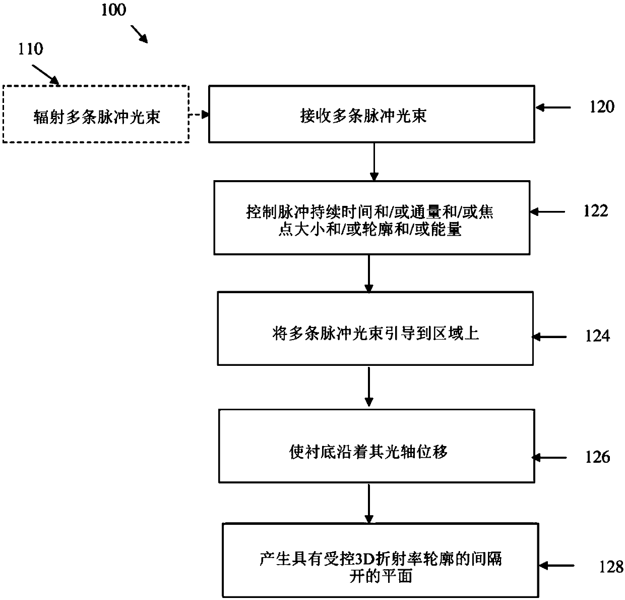
[0075] refer to figure 1 , which shows the main steps of the method 100 for writing a periodic pattern of the present invention through a flowchart. The method 100 includes step 120: receiving a plurality of beams of femtosecond laser pulses, each beam having a certain pulse duration, flux, focus size, beam profile and energy at a certain operating wavelength; step 122: controlling the plurality of beams At least one of the pulse duration, fluence, focus size, focus shape, profile and energy of the laser pulse beams; step 124: directing the plurality of laser pulse beams onto an area of ​​the substrate having an optical axis so that Thereby selectively inducing at least one of local refractive index changes, micropores, and stress-modulated regions at the point of interaction between each beam and the certain region according to the characteristics of the laser; step 126: controllably using Displacing the substrate along its optical axis to create a periodic pattern along the...


PUM

PropertyMeasurementUnit
lengthaaaaaaaaaa
lengthaaaaaaaaaa

Abstract

The present invention relates to a novel method and system for inscription of periodic patterns inside or on a surface of a substrate using femtosecond pulse lasers. The method comprises the followingsteps: (a) receiving a plurality of femtosecond laser pulsed beams, each beam having a certain pulse duration, flux, focal spot size, profile and energy at a certain wavelength of operation; (b) controlling at least one of the pulse duration, flux, focal spot size, focal spot shape, profile and energy of the plurality of laser pulsed beams; (c) directing the plurality of laser pulsed beams onto acertain region of a substrate having an optical axis, to thereby selectively induce at least one of local index change, microvoids and stress-modulated region at a point of interaction between each beam and the certain region; (d) controllably displacing the substrate along its optical axis to create the periodic patterns on a first plane of inscription along the optical axis; and (e) creating spaced-apart planes across the substrate having a controlled index profile at least in two dimensions.

Description

technical field [0001] The present invention relates to optics and photonics. In particular, the present invention relates to methods and systems for fabricating waveguides, gratings and integrated optical circuits. Background technique [0002] The fabrication of many photonic devices has been achieved by exposing transmissive and absorbing materials to intense laser radiation in order to alter the optical properties of the materials. For example, the UV-induced photosensitivity of germanium-doped silica glass has been exploited to produce permanent refractive index changes in the photosensitive Ge-doped silica core of single-mode fibers and waveguides, as opposed to the undoped cladding. By using two-beam interferometry as disclosed by Glenn et al. in U.S. Patent No. 4,807,950 or by producing spatial intensity modulation to UV exposure using a phase mask as disclosed by Hill et al. in U.S. Patent No. 5,367,588, the light-sensitive A Bragg grating (Bragg grating) structur...

Claims


Application Information

Patent Timeline
Patent Type & Authority Applications(China)
IPC IPC(8): B23K26/00B23K26/08B23K26/064B23K26/359B23K26/0622
CPCB23K26/0006B23K26/083B23K26/064B23K26/359B23K26/0624B23K2103/54B23K26/355B23K2101/40B23K2103/52B23K2103/56G02B6/124G02B6/13G02B6/02147G02B6/10B23K26/082B23K26/53B23K2101/00B23K2103/42B23K26/0608B23K26/0626B23K26/0648B23K26/0823G02B5/1857
Inventor K·卡利
Owner CYPRUS UNIV OF TECH
Why Eureka
Try Eureka