Pneumatic Tire

a technology of pneumatic tires and tyres, which is applied in the field of pneumatic tires, can solve the problems of high-speed durability degradation, tire noise, and deformation of elastic fixed bands, and achieve the effects of reducing noise, improving durability, and increasing the volume of band-like sound absorption members

Active Publication Date: 2018-11-08
THE YOKOHAMA RUBBER CO LTD
View PDF4 Cites 3 Cited by
  • Summary
  • Abstract
  • Description
  • Claims
  • Application Information

AI Technical Summary

Benefits of technology

[0005]The present technology provides a pneumatic tire that can promote heat dissipation from a band-like sound absorbing member, and improve high-speed durability, in conjunction with relieving stress occurring on the band-like sound absorbing member during a tire rolling motion, and improving the durability of the band-like sound absorbing member, by providing a cut on the band-like sound absorbing member adhered to an inner surface of the tire.
[0007]With the present technology, a plurality of cuts are formed on a band-like sound absorbing member, and both terminals of the cuts are configured to terminate at an inner side of the band-like sound absorbing member, and therefore, when a tire deflects during a tire rolling motion, the cuts of the band-like sound absorbing member open and follow deformation of the tire to relieve stress occurring on the band-like sound absorbing member, and thus damaging of the band-like sound absorbing members can be suppressed. Thereby, the durability of the band-like sound absorbing member can be improved. Furthermore, the heat dissipation area of the band-like sound absorbing member increases based on the cuts of the band-like sound absorbing member opening during a tire rolling motion, and therefore, heat dissipation from the band-like sound absorbing member can be promoted, and thus high-speed durability of the pneumatic tire can be improved. Furthermore, both terminals of the cuts terminate at the inner side of the band-like sound absorbing member, and therefore, movement of the band-like sound absorbing member can be limited, and thus damaging of the band-like sound absorbing member or rubbing between the band-like sound absorbing members can be further suppressed.
[0008]Furthermore, an angle θ of the plurality of cuts with regard to the tire circumferential direction is preferably within a range of 40°≤θ≤90°. Thereby, the cuts of the band-like sound absorbing member can open and follow deformation of the tire during a tire rolling motion, relieve stress generated on the band-like sound absorbing member, and suppress damaging of the band-like sound absorbing member. Furthermore, heat dissipation from the band-like sound absorbing member can be promoted, and high-speed durability of the pneumatic tire can be improved.
[0009]A depth d of the cuts is preferably 50% or more with regard to a thickness D of the band-like sound absorbing member. Thereby, the cuts of the band-like sound absorbing member can open during a tire rolling motion, promote heat dissipation from the band-like sound absorbing member, and improve the high-speed durability of the pneumatic tire.
[0011]A volume of the band-like sound absorbing member is preferably 10% to 30% with regard to the luminal volume of the tire. Thereby, a sound absorbing effect based on the band-like sound absorbing member can be even further achieved. An excellent noise reducing effect can be achieved by increasing the volume of the band-like sound absorbing member, and a favorable stress relieving effect and heating dissipating effect can be demonstrated even with a large band-like sound absorbing member. The luminal volume of the tire is a volume of a cavity portion formed between a tire and rim in a condition where the tire is mounted on a regular rim and inflated to a regular internal pressure “Regular rim” is a rim defined by a standard for each tire according to a system of standards that includes standards on which tires are based, and refers to a “standard rim” in the case of Japan Automobile Tyre Manufacturers Association (JATMA), refers to a “design rim” in the case of Tire and Rim Association (TRA), and refers to a “measuring rim” in the case of European Tyre and Rim Technical Organisation (ETRTO). However, when the tire is an original equipment tire, the volume of the space is calculated using a genuine wheel to which the tire is assembled. “Regular internal pressure” is the air pressure defined by standards for each tire according to a system of standards that includes standards on which tires are based, and refers to a “maximum air pressure” in the case of JATMA, refers to the maximum value in the table of “TIRE ROAD LIMITS AT VARIOUS COLD INFLATION PRESSURES” in the case of TRA, and refers to the “INFLATION PRESSURE” in the case of ETRTO. However, the air pressure which is displayed on the vehicle is used in a case where the tire is an original equipment tire.
[0012]The band-like sound absorbing member preferably has a missing portion in at least one section in the tire circumferential direction. Thereby, long-term resistance is possible against expansion due tire inflation and shear strain of an adhering surface caused by a ground-contacting rolling motion.

Problems solved by technology

Cavernous resonance caused by the vibration of the air filled in a cavity portion of a tire is one cause of tire noise.
However, if securing the sound absorbing member is dependent on the elastic fixed band, problems occur where the elastic fixed band deforms during high speed travel.
However, in this case, the band-like sound absorbing member is directly applied to a tire inner surface, and therefore, problems occur where heat accumulation is generated on a tread portion, and high-speed durability deteriorates due to heat accumulation.
Furthermore, if the band-like sound absorbing member is directly applied on a tire inner surface, problems occur where the band-like sound absorbing member cannot follow tire deflection during a tire rolling motion and therefore is damaged.
Furthermore, both terminals of the cuts terminate at the inner side of the band-like sound absorbing member, and therefore, movement of the band-like sound absorbing member can be limited, and thus damaging of the band-like sound absorbing member or rubbing between the band-like sound absorbing members can be further suppressed.

Method used


Image

  • Pneumatic Tire
  • Pneumatic Tire
  • Pneumatic Tire

Examples


examples

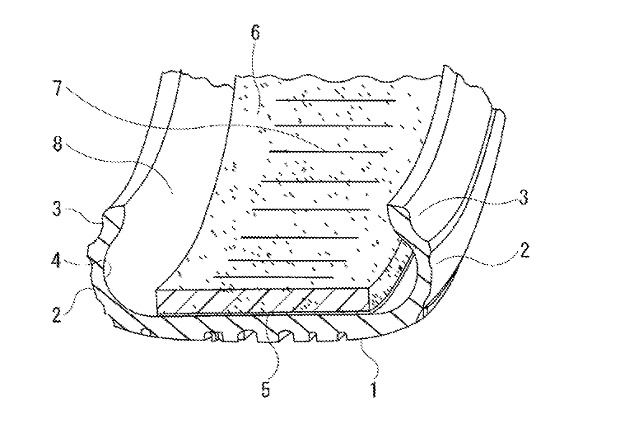
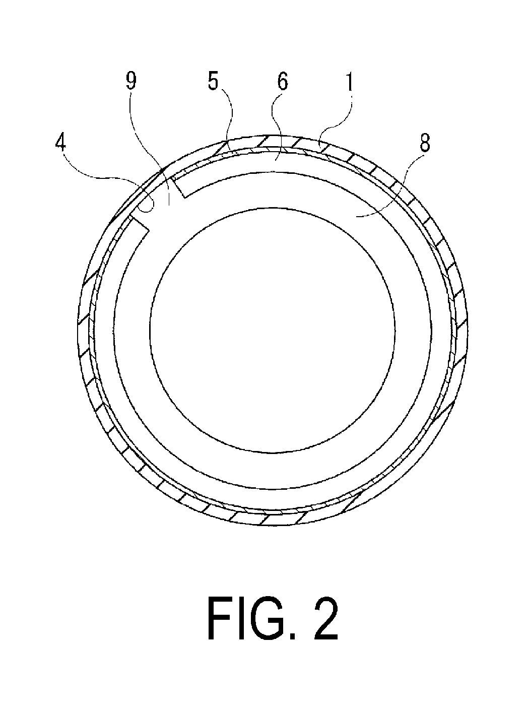
[0030]Tires of a Conventional Example, Comparative Example 1, and Examples 1 to 11 where the presence of the cuts, placement of the cuts, angle θ of the cuts, depth of the cuts (depth d / thickness D×100%), and width of the cuts (width a / width A×100%) were set as shown in Table 1-1 and Table 1-2, were prepared for a pneumatic tire with a tire size of 275 / 35ZR20 provided with an annular-shaped tread portion extending in a tire circumferential direction, a pair of sidewall portions disposed on both sides of the tread portion, and a pair of bead portions disposed on an inner side in a tire radial direction of the sidewall portions, where a band-like sound absorbing member is adhered on an inner surface of the tread portion in the tire circumferential direction.

[0031]The high-speed durability and the durability of the band-like sound absorbing member during high deflection (rubbing between the band-like sound absorbing members and peeling of an adhering surface) were evaluated for the tes...


PUM


Abstract

A pneumatic tire includes: an annular-shaped tread portion extending in a tire circumferential direction; a pair of sidewall portions disposed on both sides of the tread portion; and a pair of bead portions disposed on an inner side in a tire radial direction of the sidewall portions; and a band-like sound absorbing member being adhered on an inner surface of the tread portion in the tire circumferential direction; wherein the band-like sound absorbing member has a plurality of cuts, and both terminals of the cuts terminate at an inner side of the band-like sound absorbing member.

Description

TECHNICAL FIELD[0001]The present technology relates to a pneumatic tire, and particularly relates to a pneumatic tire that can promote heat dissipation from a band-like sound absorbing member, and improve high-speed durability, in conjunction with relieving stress occurring on the band-like sound absorbing member during a tire rolling motion, and improving the durability of the band-like sound absorbing member, by providing a cut on the band-like sound absorbing member adhered to an inner surface of the tire.BACKGROUND ART[0002]Cavernous resonance caused by the vibration of the air filled in a cavity portion of a tire is one cause of tire noise. Cavernous resonance is caused by a tread portion of a tire contacting a road surface during vehicle travel vibrating due to unevenness on the road surface, and the vibration is caused by air inside a cavity portion of a tire vibrating. The cavernous resonance has a frequency range where noise is generated, and reducing the noise level of the...

Claims


Application Information

Patent Timeline
Patent Type & Authority Applications(United States)
IPC IPC(8): B60C19/00B60C5/00
CPCB60C19/002B60C5/002B29D30/0681B60B2900/133
Inventor HOSHIBA, TAKASHI
Owner THE YOKOHAMA RUBBER CO LTD
Why Eureka
Try Eureka