Oil Level Sensor Tank for Turbine Engine
a technology of oil level sensor and turbine engine, which is applied in the direction of engine lubrication, liquid/fluent solid measurement, engine fuction, etc., can solve the problem of limited precision of measuring the level of fluid in this shap
- Summary
- Abstract
- Description
- Claims
- Application Information
AI Technical Summary
Benefits of technology
Problems solved by technology
Method used
Image
Examples
second embodiment
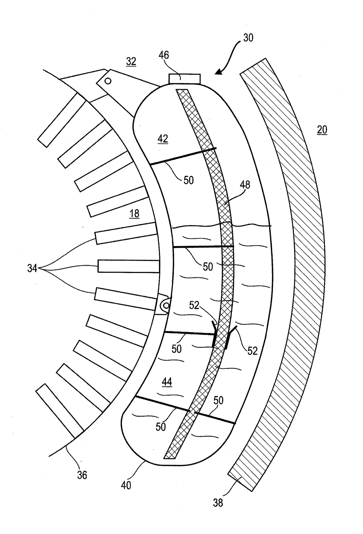
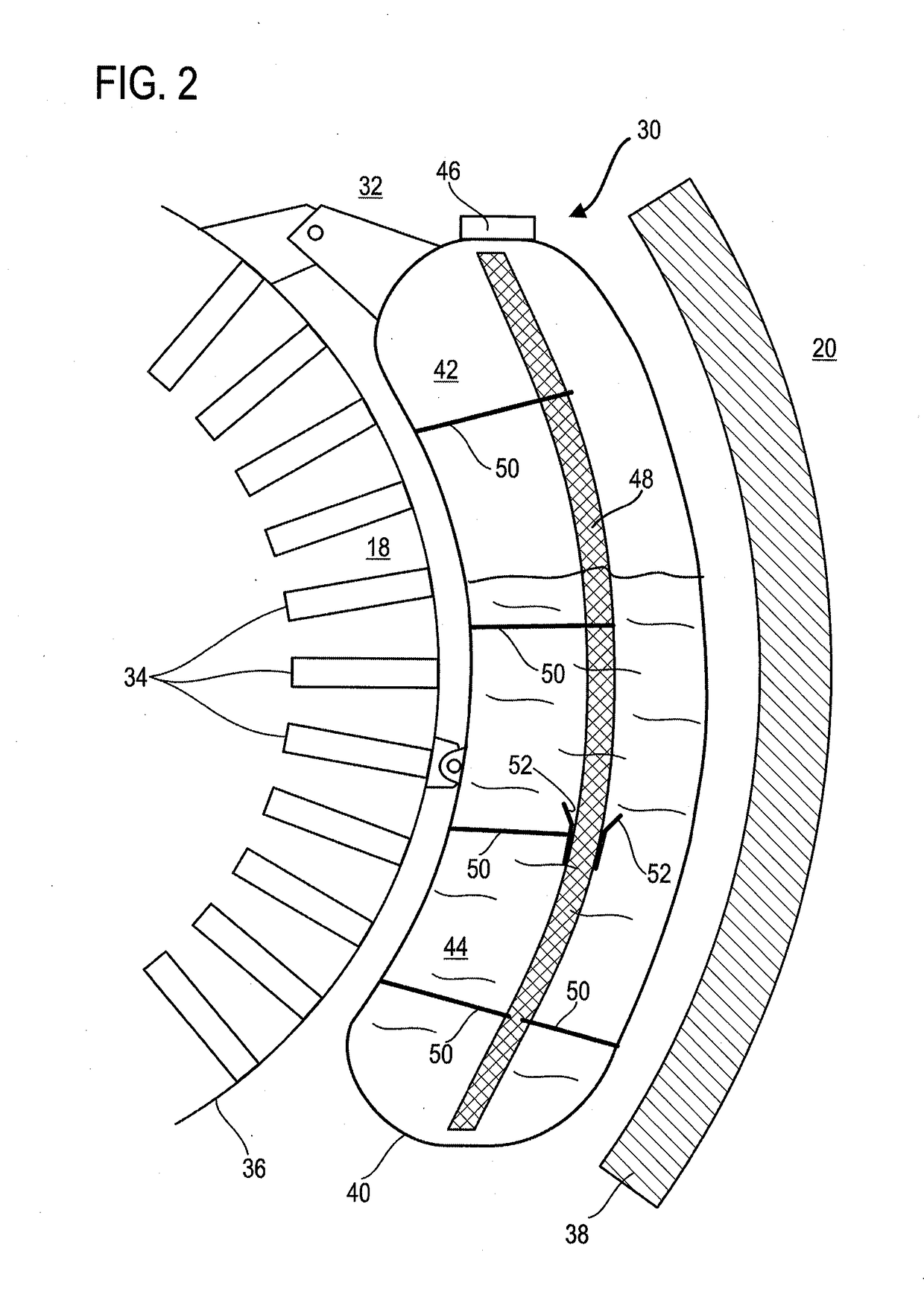
[0077]FIG. 3 outlines the tank 130 according to the present application. This FIG. 3 reuses the numbering of the preceding figures for identical or similar elements, however with the numbering being incremented by 100. Specific numbers are used for elements specific to this embodiment.
[0078]The reservoir 130 includes an arched sleeve 160. The latter is placed in the cavity 142. It can extend continuously over the majority or over substantially the entire length, for example the height, of the cavity 142 and / or of the sensor 148. The sleeve 130 can be apertured to facilitate the inlet and the outlet of the oil, such as to come into contact with the sensor 148.
[0079]The cavity of the sleeve 160 receives the sensor 148. They can be adjusted with respect to one another in order to fasten the sensor. The fixing elements can supplement this fastening. The sleeve 160 can be fixed at least at one or at each of the opposite ends thereof. These ends, for example lower and upper, can correspon...
first embodiment
[0081]Possibly, the sleeve can be held by the supporting arms such as those of the present application. Consequently, the sensor would be held indirectly by the supporting arms since it is firstly in contact with the sleeve.
[0082]The sensor can be held in a combined manner, i.e. both via the supporting arms of the first embodiment of the present application, and via one or more sleeves of the second embodiment. For example, the upper half of the sensor is held by one or more supporting arms, and the lower half is held by a sleeve, or vice versa.
[0083]FIG. 4 shows a sleeve 160 such as that of FIG. 3; however, the sleeve 160 is shown in a straight, and not arched, configuration.
[0084]The sleeve 160 is generally tubular. It can be made more flexible using cut-outs 162 which further improve the flow of the oil through the skin thereof. The cut-outs 162 are distributed, possibly homogenously, over the length of the sleeve 160. The cut-outs 162 can be arranged perpendicular to the axis of...
third embodiment
[0086]FIG. 5 shows a sleeve 260 according to the present application. This FIG. 5 reuses the numbering of the preceding figures for identical or similar elements, however with the numbering being incremented by 200. Specific numbers are used for the elements specific to this embodiment.
[0087]The cut-outs 262 divide the sleeve 260 into several mobile segments 264. Each cut-out 262 describes a closed loop around the sleeve 260. The segments 264 are hinged and mobile with respect one another. They can comprise pivot connections 266 which allow them to be attached to one another, and thus to form a chain. The pivots 266 can be formed via notches 268 receiving heads 270. The rounded contours thereof help the pivoting movement. The necking of the notches 268 coupled with the narrowing of the heads 270 allow retention along the axis of the sleeve 260. The heads 270, like the notches 268, and therefore the pivots, can be formed thanks to the cut-outs 262, which are advantageously produced b...
PUM
 Abstract
Description
Claims
Application Information
 - R&D
- Intellectual Property
- Life Sciences
- Materials
- Tech Scout
- Unparalleled Data Quality
- Higher Quality Content
- 60% Fewer Hallucinations
Browse by: Latest US Patents, China's latest patents, Technical Efficacy Thesaurus, Application Domain, Technology Topic, Popular Technical Reports.
© 2025 PatSnap. All rights reserved.Legal|Privacy policy|Modern Slavery Act Transparency Statement|Sitemap|About US| Contact US: help@patsnap.com


