
Hybrid plug connector

a plug connector and hybrid technology, applied in the direction of relieving strain on the wire connection, electrical equipment, two-part coupling devices, etc., can solve the problems of preventing desired miniaturization, assembling and incorporating lines into hybrid plug connectors, and providing continuous uninterrupted shielding,

Active Publication Date: 2018-11-08
BECKHOFF AUTOMATION GMBH +1
View PDF3 Cites 6 Cited by
  • Summary
  • Abstract
  • Description
  • Claims
  • Application Information

AI Technical Summary

Benefits of technology

The invention provides a versatile hybrid plug connector that can be used to connect electronic modules with different functions in manufacturing plants. The plug connectors have a modular structure that allows them to be designed in different ways without special tools. This design also provides additional polarity reversal protection for special applications. The plug contacts can be designed as pins or sockets for data or power, making the connector suitable for a variety of applications.

Problems solved by technology

While this configuration facilitates the manufacturing of plug connectors which meet the electrical requirements plug connectors have to meet, their dimensions prevent desired miniaturization.
Assembling and incorporating the lines into the hybrid plug connectors and providing continuous uninterrupted shielding can be problematic in this respect.
If individual wires stick out after unraveling, this can result in contact closing and failure of the plug connector.
Another problem of unraveling is that individual wires are tom off, and effective shielding is no longer provided when a plug has been assembled.
This means that, with the known sleeves, it is difficult to achieve continuous and all-round shielding on the one hand, and there are problems with strain relief and / or connecting the shield via the shielding sleeve on the other hand.
Axial insertion of the shielding braid is a problem, since individual wires can break off and adversely influence shielding.
Tensile strain can also result parts of the braid being torn off, causing gaps in the shielding.

Method used


Image

  • Hybrid plug connector
  • Hybrid plug connector
  • Hybrid plug connector

Examples


Embodiment Construction

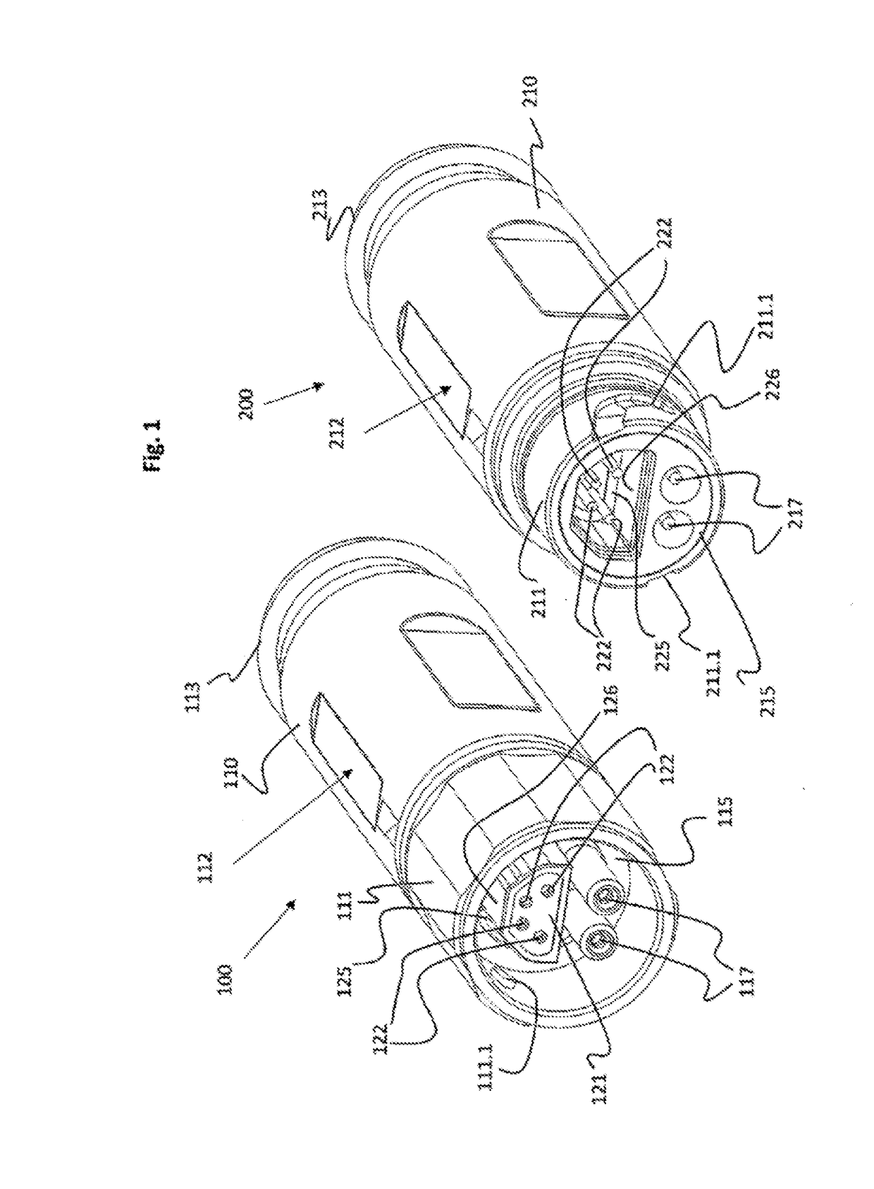
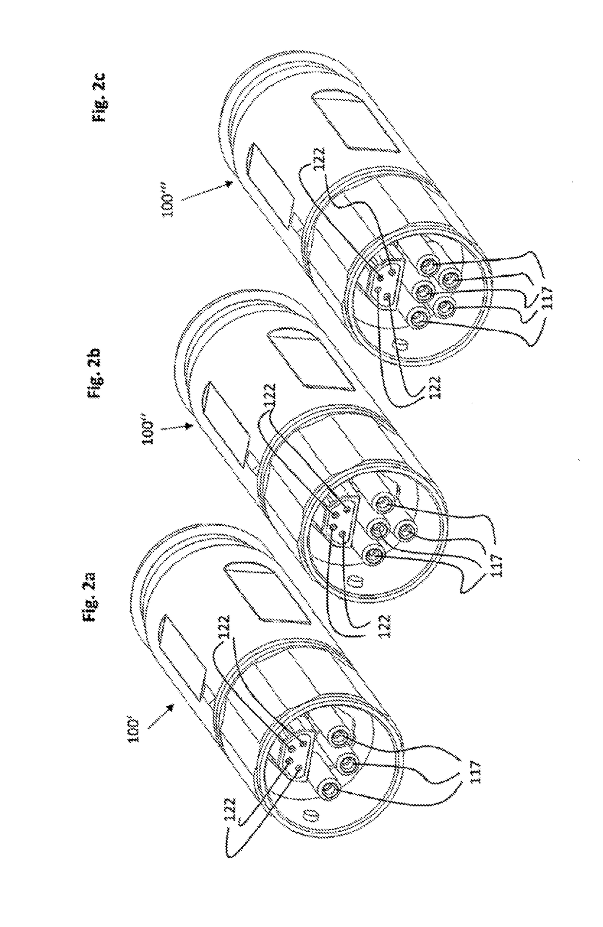
[0033]It will be understood that the respective corresponding plug connectors 200 have identical plug configurations, but with plug pins 222 or 217, respectively. The data conductor, which according to the exemplary embodiment has four data lines, may also include 1, 2, or 3 data lines. It is also possible that more than 4 data lines are arranged in the data conductor, all of which are contacted in the shield housing 125 or 225, respectively.

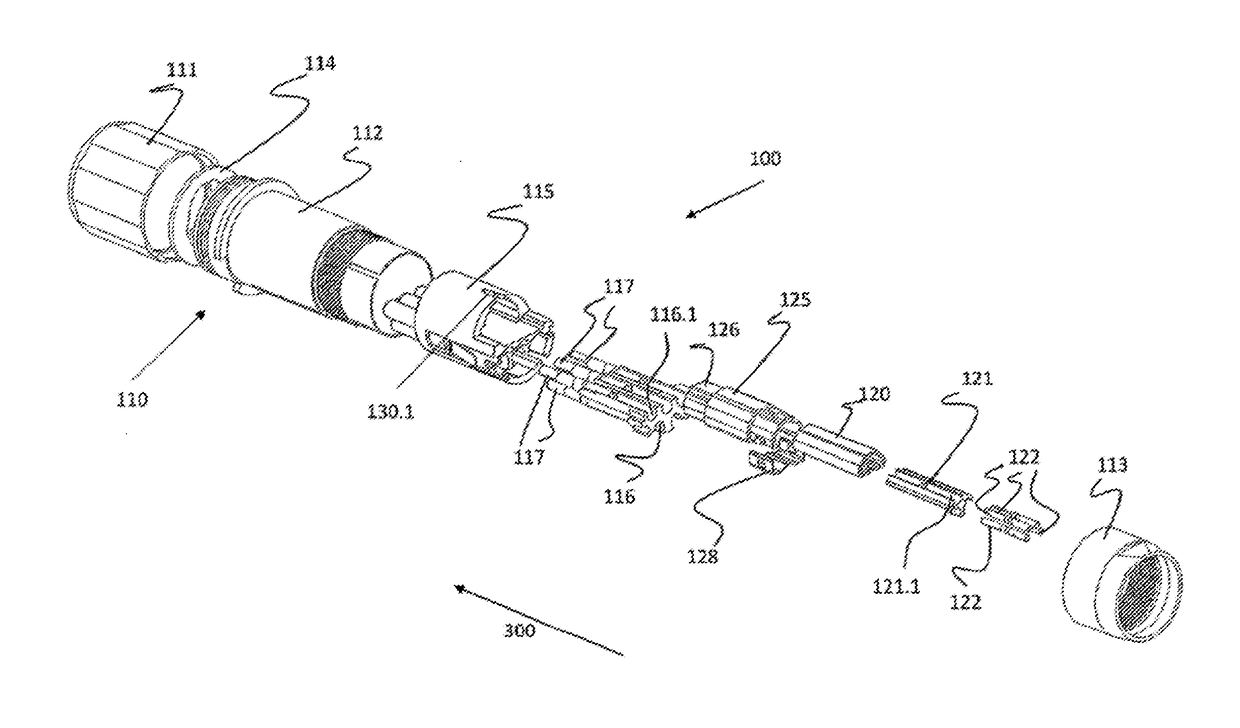
[0034]FIG. 3, in conjunction with FIG. 4, shows the structure of the plug connector 100′ plug sockets 117, wherein it also becomes apparent how the plug connector 100′″ is assembled. Structure and assembly apply likewise to the plug connectors 100, 100′, 100″, 200, of course. If a cable, which is not shown here, is connected to the plug connector 100′″, the five wires of the power line, according to the exemplary embodiment of FIG. 3, should be connected to the plug sockets 117 of the power contacts and be clipped onto the contact carrier 116. s...


PUM


Abstract

Hybrid plug connectors are provided for connecting different electronic modules to insulators arranged in an outer casing and for receiving a power conductor transmitting a power supply and a shielded data conductor for data transmission for transmitting signals / data of an industrial bus, such as ISA, ethernet or similar, wherein the power conductor has at least two power lines and the data conductor has at least one data line, wherein the power lines and the data lines are guided in contact parts designed as plugs or sockets and can be coupled via these contacts parts, and wherein the outer casings of the pair-type hybrid plug connectors can be joined inside one another for interlocking coupling. The insulator arranged in each of the plug connectors can be arranged in a shield housing as a contact carrier receiving arrangement, the shield housing accommodating a contact carrier, which carries forward the data line(s) designed as plug sockets or plug pins in a shielded manner in the plug connector, and wherein the coupleable contacts form a shape-encoded interlocking connection in the plugged-in state of the connection.

Description

BACKGROUND AND SUMMARY[0001]The invention relates to a hybrid plug connector for connecting conductor cables of different electronic modules to insulator bodies arranged in an outer casing for receiving a power conductor transmitting a power supply and a shielded data conductor for data transmission for transmitting signals / data of an industrial bus, such as ISA, Ethernet, or the like, wherein the power conductor has at least two power lines and the data conductor has at least one data line, wherein the power lines and the data lines are guided in contact parts designed as plugs or sockets and can be coupled via these contacts parts, and wherein the outer casings of the hybrid plug connectors can be joined inside one another for interlocking coupling, and wherein an insulator body designed as a contact carrier receiving means is arranged in each of the plug connectors designed as sockets and plugs, having a contact carrier in a shield housing, said shield housing accommodating a con...

Claims


Application Information

Patent Timeline
Patent Type & Authority Applications(United States)
IPC IPC(8): H01R13/6592H01R13/642H01R13/514H01R13/58
CPCH01R13/6592H01R13/642H01R13/514H01R13/582H01R2103/00H01R24/86
Inventor VOGEL, FLORIANRETTIG, THOMASBECHTEL, DIRKSCHMIDT, WERNERSCHRAMM, CHRISTIAN
Owner BECKHOFF AUTOMATION GMBH
Learn More