Three-Dimensional Modeling Apparatuses And Methods For Fabricating Three-Dimensional Objects
- Summary
- Abstract
- Description
- Claims
- Application Information
AI Technical Summary
Benefits of technology
Problems solved by technology
Method used
Image


Examples
first embodiment
A. First Embodiment
[0025]FIG. 1 is an explanatory view of a schematic configuration of a three-dimensional modeling apparatus 10 of a first embodiment of the present invention. The three-dimensional modeling apparatus 10 includes an ejection unit 100, a platform 200, and a control unit 300. FIG. 1 indicates three directions X, Y, and Z perpendicular to each other. The X direction and the Y direction are horizontal directions, and + the Z direction is a vertically upward direction. These directions are indicated as necessary in other drawings as well. Hereinafter, +Z direction is also referred to as an “upper side,” and −Z direction is also referred to as a “lower side.”
[0026]The ejection unit 100 includes a screw case 15, a hopper 20 that accommodates a material, a drive motor 30, a flat screw 40, a heating unit 50, an ejection section 60 having a nozzle 61 for ejecting a molten material, and an air blowing unit 70. The flat screw 40 and the heating unit 50 constitute a plasticizing...
second embodiment
B. Second Embodiment
[0046]In the first embodiment, air is uniformly blown from the entire circumference of the nozzle 61 by the air blowing unit 70. On the other hand, in the second embodiment, the control unit 300 controls the direction of air flow from the air blowing unit.
[0047]FIG. 9 is an explanatory view of a schematic configuration of an air blowing unit 70a of the second embodiment. FIG. 9 illustrates positioning of air outlets of the air blowing unit 70a as viewed from the above (on the +Z direction-side). A first air blowing section 71a of the present embodiment includes a plurality of first air outlets 77 disposed around the nozzle 61 to perform blowing of air toward the molten material ejected from the nozzle 61. The flow rate of the first air outlets 77 can be each adjusted. In the present embodiment, eight first air outlets 77 are disposed around the nozzle 61 at a constant angular interval. Compressed air is supplied to the respective first air outlets 77 via a piping...
third embodiment
C. Third Embodiment
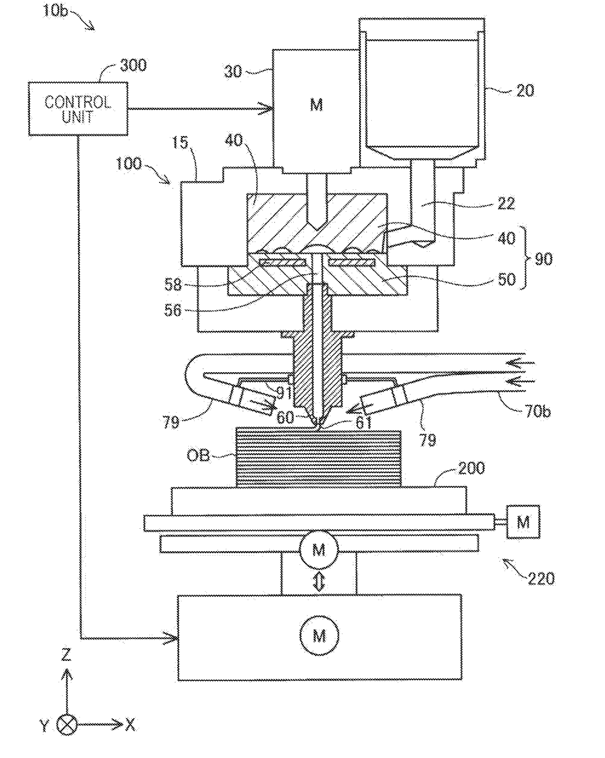
[0056]FIG. 12 is an explanatory view of a schematic configuration of the three-dimensional modeling apparatus 10b of the third embodiment of the present invention. The third embodiment differs from the other embodiments in the configuration of the air blowing unit.
[0057]As shown in FIG. 12, an air blowing unit 70b of the present embodiment includes four tubes 79 disposed around the nozzle 61 (ejection section 60) at a constant angular interval. For convenience of illustration, only two tubes 79 are shown in FIG. 12. These tubes 79 are, for example, fixed to the ejection section 60 or the screw case 15 by a clamp 91 or the like. Each tube 79 has a function corresponding to the first air blowing section 71 of the first embodiment. Therefore, compressed air is introduced into the respective tubes 79 so that air is blown from the end of each tube 79 toward the molten material ejected from the nozzle 61.
[0058]As shown in the present embodiment, the temperature of the m...
PUM
| Property | Measurement | Unit |
|---|---|---|
| Flow rate | aaaaa | aaaaa |
| Circumference | aaaaa | aaaaa |
Abstract
Description
Claims
Application Information