Control method and control device of internal combustion engine

Active Publication Date: 2018-11-15
NISSAN MOTOR CO LTD +1
View PDF39 Cites 4 Cited by
  • Summary
  • Abstract
  • Description
  • Claims
  • Application Information

AI Technical Summary

Benefits of technology

[0004]An object of the present invention is to improve ignitabili

Problems solved by technology

However, the tumble flow is gradually weakened as the compression stroke progresses and is broken in the end and thus, even if the tumble flow is reinforced as in the aforementioned document, the tumble flow cannot be maintained till ignition timing easily.
Then, the weaker a gas flow in the cylinder is at the ignition timing, the

Method used


Image

  • Control method and control device of internal combustion engine
  • Control method and control device of internal combustion engine
  • Control method and control device of internal combustion engine

Examples


Example

First Embodiment

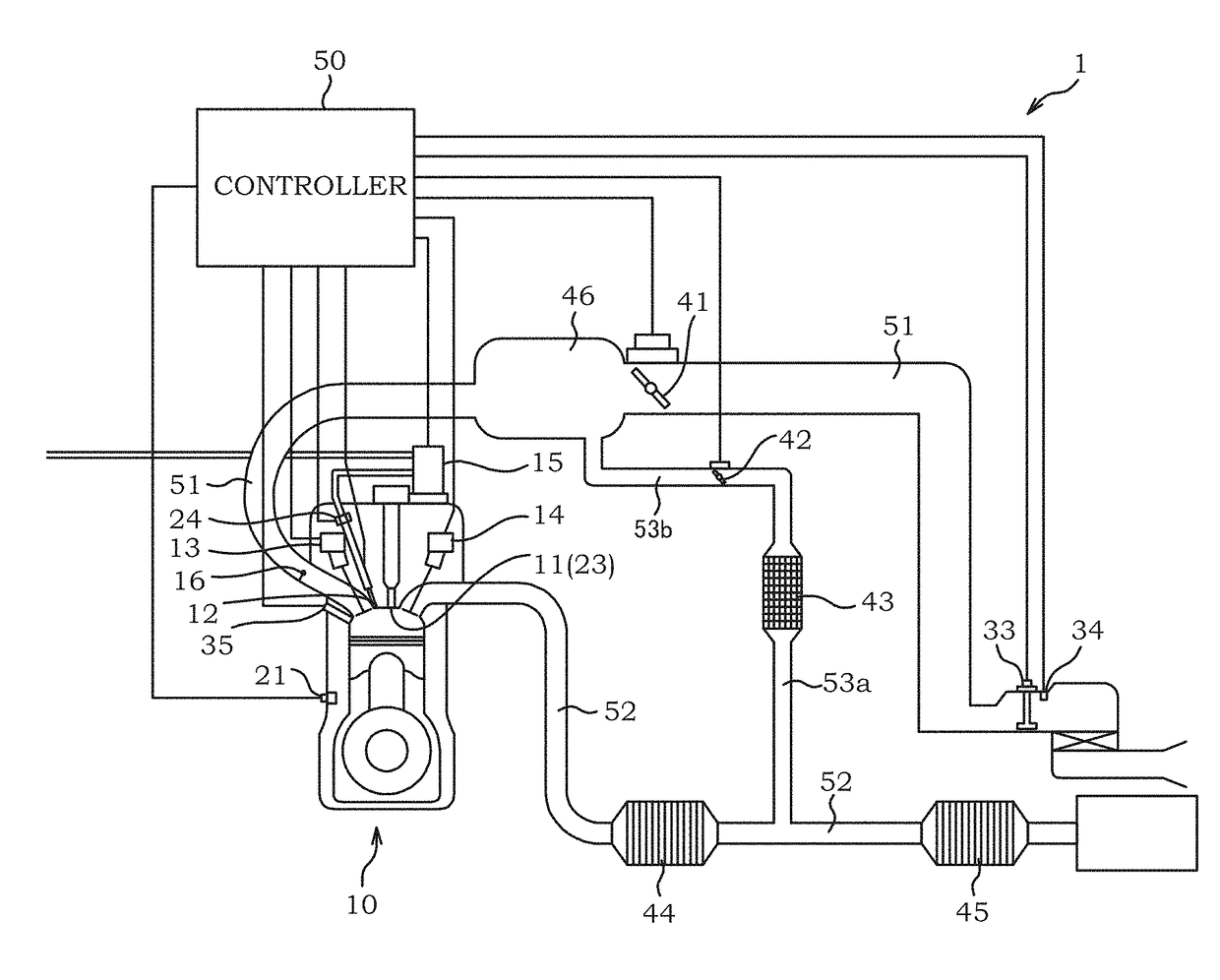
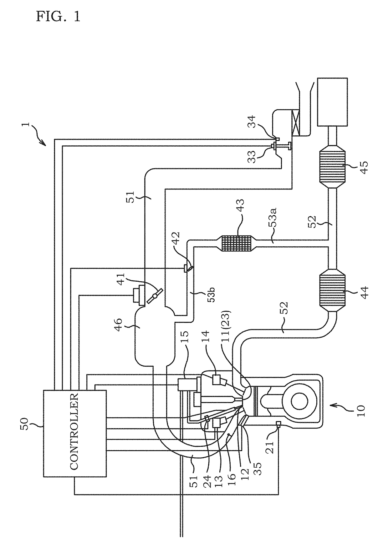
[0036]FIG. 1 is an explanatory view of entire configuration of an internal combustion engine system. In the internal combustion engine system 1, an internal combustion engine 10 is connected to an intake passage 51. The internal combustion engine 10 is also connected to an exhaust passage 52.

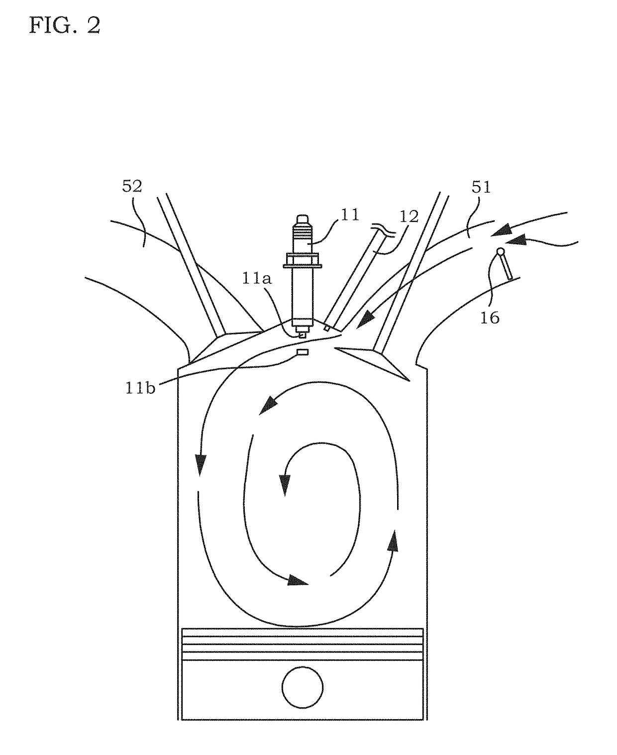
[0037]In the intake passage 51, a tumble control valve 16 is provided. The tumble control valve 16 generates tumble fluidity in a cylinder by closing a part of a channel section of the intake passage 51.

[0038]In the intake passage 51, a collector tank 46 is provided. To the collector tank 46, an EGR passage 53b is connected.

[0039]In the intake passage 51, an air flow meter 33 is provided. A controller 50 connected to the air flow meter 33 obtains an intake amount in the intake passage 51 from an air flow meter 33. Moreover, in the intake passage 51, an intake temperature sensor 34 is provided. The controller 50 connected to the intake temperature sensor 34 obtains a temperature o...

Example

Second Embodiment

[0118]This embodiment is similar to the first embodiment in terms of basic configuration and control of extending the plug discharging channel, but forms of spray beams B1 to B6 are different from the first embodiment.

[0119]FIG. 23 is a view illustrating a positional relationship between the spray beams B1 to B6 and the ignition plug 11 in this embodiment.

[0120]In the first embodiment, the spray beams B1 to B6 are formed at equal intervals, but in this embodiment, an angle a formed by the spray beam B2 and the spray beam B3 is smaller than an angle y formed by the spray beam B2 and the spray beam B1 and an angle β formed by the spray beam B3 and the spray beam B4. The angle formed by two spray beams is an angle between center axes of the respective spray beams.

[0121]As a result, the spray beam B2 is drawn to the spray beam B3 more strongly than the spray beam B1, and the spray beam B3 is drawn to the spray beam B2 more strongly than the spray beam B4. As a result, a...

Example

Third Embodiment

[0123]This embodiment is similar to the first embodiment in terms of basic configuration and control for extending the plug discharging channel, but a positional relationship between the spray beam B2 and the spray beam B3 sandwiching the ignition plug 11 is different from the first embodiment.

[0124]In the first embodiment, when seen from an arrow XII direction in FIG. 10, the spray beam B2 and the spray beam B3 overlap each other. However, in this embodiment, assuming that an angle formed by a reference line in parallel with a cylinder axis and passing through an injection hole and the spray beam B2 is θ1 and an angle formed by the reference line and the spray beam B3 is θ2 as illustrated in FIG. 24, it is θ1≠θ2.

[0125]When a mechanism for maintaining one of the intake valves in a closed valve state without operating it in accordance with the operating state is provided in an intake double-valve internal combustion engine 10 or when in-cylinder fluidity is in a state...


PUM


Abstract

In a control method of an internal combustion engine including a fuel injection valve having a plurality of injection holes and adapted to directly inject a fuel into a cylinder and an ignition plug adapted to generate a plug discharging channel, after fuel injection is performed, spark ignition is performed while turbulence in an air flow is generated by the fuel injection by an ignition plug disposed so that a discharging region is sandwiched by fuel sprays injected from the two adjacent injection holes and located within a range where the turbulence in the air flow is generated.

Description

TECHNICAL FIELD[0001]The present invention relates to a control method and a control device of an internal combustion engine.BACKGROUND ART[0002]JP2009-85012A discloses improvement of homogeneity of a mixture in a cylinder by performing main fuel injection during an intake stroke and by performing sub fuel injection during a compression stroke so as to reinforce tumble flow.SUMMARY OF INVENTION[0003]However, the tumble flow is gradually weakened as the compression stroke progresses and is broken in the end and thus, even if the tumble flow is reinforced as in the aforementioned document, the tumble flow cannot be maintained till ignition timing easily. Then, the weaker a gas flow in the cylinder is at the ignition timing, the lower the combustion stability becomes. That is, the homogeneity of the mixture in the cylinder can be improved by reinforcing the tumble flow as in the aforementioned document, but even if the mixture is homogenized, reliable ignition cannot be expected withou...

Claims


Application Information

Patent Timeline
IPC IPC(8): F02B23/10F02M61/14F02D9/08F02P5/04F02P5/15F02M61/18
CPCF02B23/10F02M61/14F02D9/08F02P5/045F02P5/15F02M61/1806F02B2023/106F02B2023/103F02B2275/48F02D37/02F02D41/403F02D35/023F02P5/1502F02D41/1498F02D2250/31Y02T10/12F02B23/06F02B23/08F02P13/00
Inventor IWABUCHI, YOSHIHIKOTANAKA, DAISUKEUCHIDA, RYO
Owner NISSAN MOTOR CO LTD
Why Eureka
Try Eureka