
Improvements in or relating to tire testing procedures

a technology for tyres and testing procedures, applied in vehicle testing, structural/machine measurement, instruments, etc., can solve the problems of high cost, complex non-linear behaviour, and challenging components to model, so as to save test time, save test time, and achieve the effect of reducing the cost of testing

Active Publication Date: 2018-11-15
JAGUAR LAND ROVER LTD
View PDF0 Cites 5 Cited by
  • Summary
  • Abstract
  • Description
  • Claims
  • Application Information

AI Technical Summary

Benefits of technology

The invention provides a method of testing a tyre on a moving surface to collect data for modelling the tyre. This method involves steering the tyre with respect to the surface while applying load to the tyre based on its slip angle. This approach mimics the loading conditions experienced by the tyre in real life, resulting in accurate data capture and saving time during the testing process. The load on the tyre may be maintained at a constant level during movement, allowing for progressive load variation at different slip angle positions. The method ensures accurate and efficient testing of the tyre to ensure its performance meets the requirements of the vehicle.

Problems solved by technology

In physical testing, the need for fully assembled test cars, drivers, venues and fuel leads to very high costs, acting as a barrier to automotive companies using these techniques.
One of the most challenging components to model is the tyre, which exhibits complex, non-linear behaviour.
A clear disadvantage of this method is the high number of sweeps that are required to collect the necessary data.
For example, given four loads, three cambers, three inflation pressures, and combined testing at three different slip angles, the square matrix approach would require a total of 144 separate sweeps to be undertaken, which is time consuming and, hence, costly.

Method used


Image

  • Improvements in or relating to tire testing procedures
  • Improvements in or relating to tire testing procedures
  • Improvements in or relating to tire testing procedures

Examples


Embodiment Construction

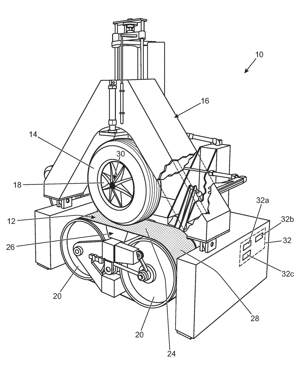
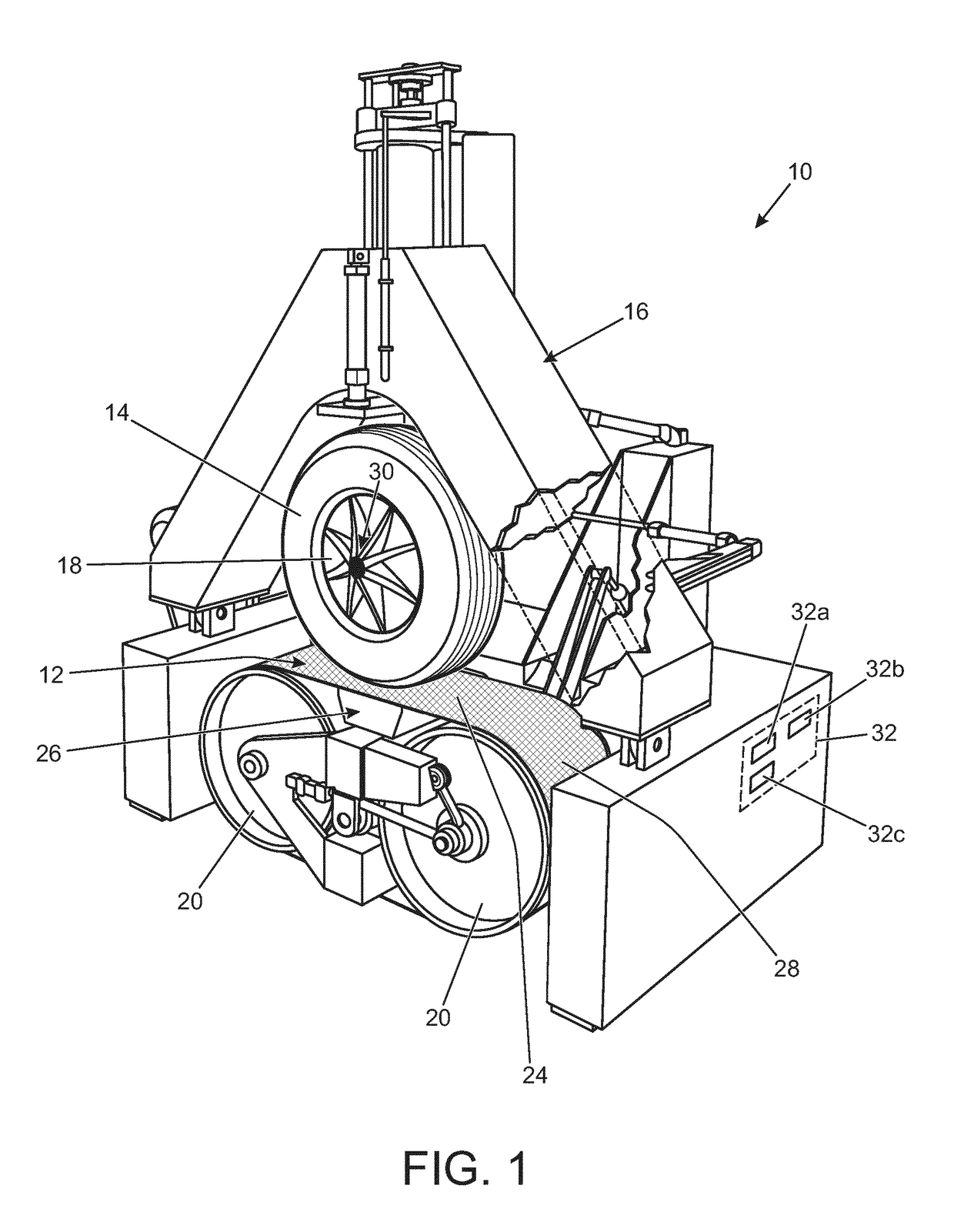
[0034]As has already been discussed, modelling of tyre behaviour in the context of a wider vehicle dynamic model is a known technique. A commonly known form of tyre model is the Magic Formula (MF) 6.1 model, although this is provided here only as an example since other tyre models are available in the art, but similar principles apply.

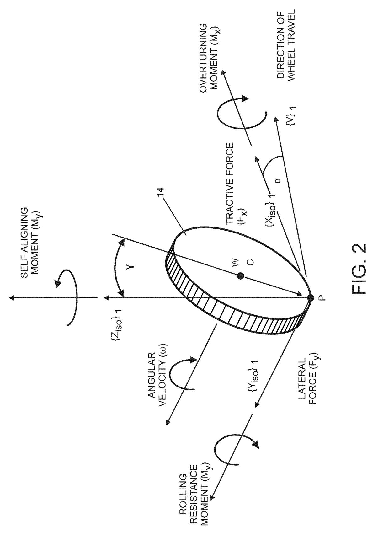
[0035]In such models, it is typical to use vertical load, camber angle, and slip angle as inputs. As is known, the camber angle is the measure in degrees of the difference between the wheels vertical alignment and the axis perpendicular to the surface, when viewed from the front of the vehicle. When the wheel is perpendicular to the surface the camber angle is 0°. The camber angle is negative when the top of the wheel is tilted towards the vehicle and positive for the opposite situation. The slip angle is the angle between the direction of travel of a rolling wheel and the direction in which the wheel is pointing. References to these terms in this desc...


PUM


Abstract

A method of performing a test on a tyre to record data for parameterisation of a tyre model, wherein the method is performed on a tyre mounted on a wheel and supported on a mobile axle with respect to a movable testing surface. The method includes supporting the tyre with respect to the movable test surface such that the slip angle of the tyre is controllable and such that the loading on the tyre is controllable, steering the tyre with respect to the test surface so as to vary the tyre slip angle, and applying load to the tyre in dependence on tyre slip angle so as to simulate real life tyre loading conditions. Aspects and embodiments of the invention also provide a computer program product and a machine readable medium. Beneficially, the method results in a tyre being tested under more realistic conditions since the applied tyre loading varies in dependence on the tyre slip angle, thereby mimicking the loading on the tyre experienced as vehicle weight transfers during cornering. This ensures that accurate tyre performance data representing the real-life performance envelope of the tyre is captured during testing, whilst test time can be saved by not testing load cases which the tyre will never experience on a real vehicle.

Description

TECHNICAL FIELD[0001]The present disclosure relates to improvements in or relating to tyre testing procedures, and in particular, but not exclusively, to a method of performing a test on a tyre in order to record data electronically for parameterisation of a tyre model. The method is performed on a computer controlled, programmable, tyre testing apparatus. Thus, the disclosure also relates to a computer program product that is configured for implementing the method, and a machine readable medium having stored thereon such a computer program product. Aspects of the invention relate to a method of performing a test on a tyre to record data for parameterisation of a tyre model and a tyre testing apparatus.BACKGROUND[0002]Manufacturers in the automotive industry are striving continually to provide vehicles with enhanced design and performance features in order to meet with the growing demands of consumers. Furthermore, the sector must comply with increasingly strict government regulatio...

Claims


Application Information

Patent Timeline
Patent Type & Authority Applications(United States)
IPC IPC(8): G01M17/02
CPCG01M17/022G01M17/02
Inventor SMITH, GREGORYOLSSON, HENNING
Owner JAGUAR LAND ROVER LTD
Learn More