Auto-linking of function logic state with testcase regression list

a function logic and testcase technology, applied in the field of logic design testing, can solve the problems of inefficiency of process, high processing cost, and rarely complete prediction, and achieve the effect of saving test time and resources

Inactive Publication Date: 2005-05-05
IBM CORP
View PDF3 Cites 3 Cited by
  • Summary
  • Abstract
  • Description
  • Claims
  • Application Information

AI Technical Summary

Benefits of technology

[0007] The present invention is directed to a method and system for identifying logic function areas, which make up a virtual machine, that are affected by specific testcases. A Hardware Descriptor Language (HDL) is used to create a software model of the virtual machine. A simulator compiles and analyzes the HDL model, and creates a matrix scoreboard identifying logic function areas in the virtual machine. A complete list of testcases is run on the virtual machine while a monitor correlates each testcase with affected logic function areas to fill in the matrix scoreboard. When a subsequent test failure occurs, either because of a modification to a logic function area, or the execution of a new test, all logic function areas that are affected, either directly or indirectly, are identified. This accurate identification allows a tester to correct only such affected logic areas, thus resulting in a savings in test time and resources.

Problems solved by technology

Although an AVP may be useful in determining if an entire virtual machine is working, erroneous outputs from the virtual machine alone do not identify which FSM or FSMs are responsible for the failure.
While documentation comments in the AVP may attempt to identify affected FSMs and thus the source of the failure, such predictions are rarely complete due to unexpected consequences of test software on FSM architecture, as well as unexpected anomalies in the FSM architecture itself.
Such a process is very time consuming, as a full AVP may take days to run, making such a process inefficient.

Method used


Image

  • Auto-linking of function logic state with testcase regression list
  • Auto-linking of function logic state with testcase regression list
  • Auto-linking of function logic state with testcase regression list

Examples


Embodiment Construction

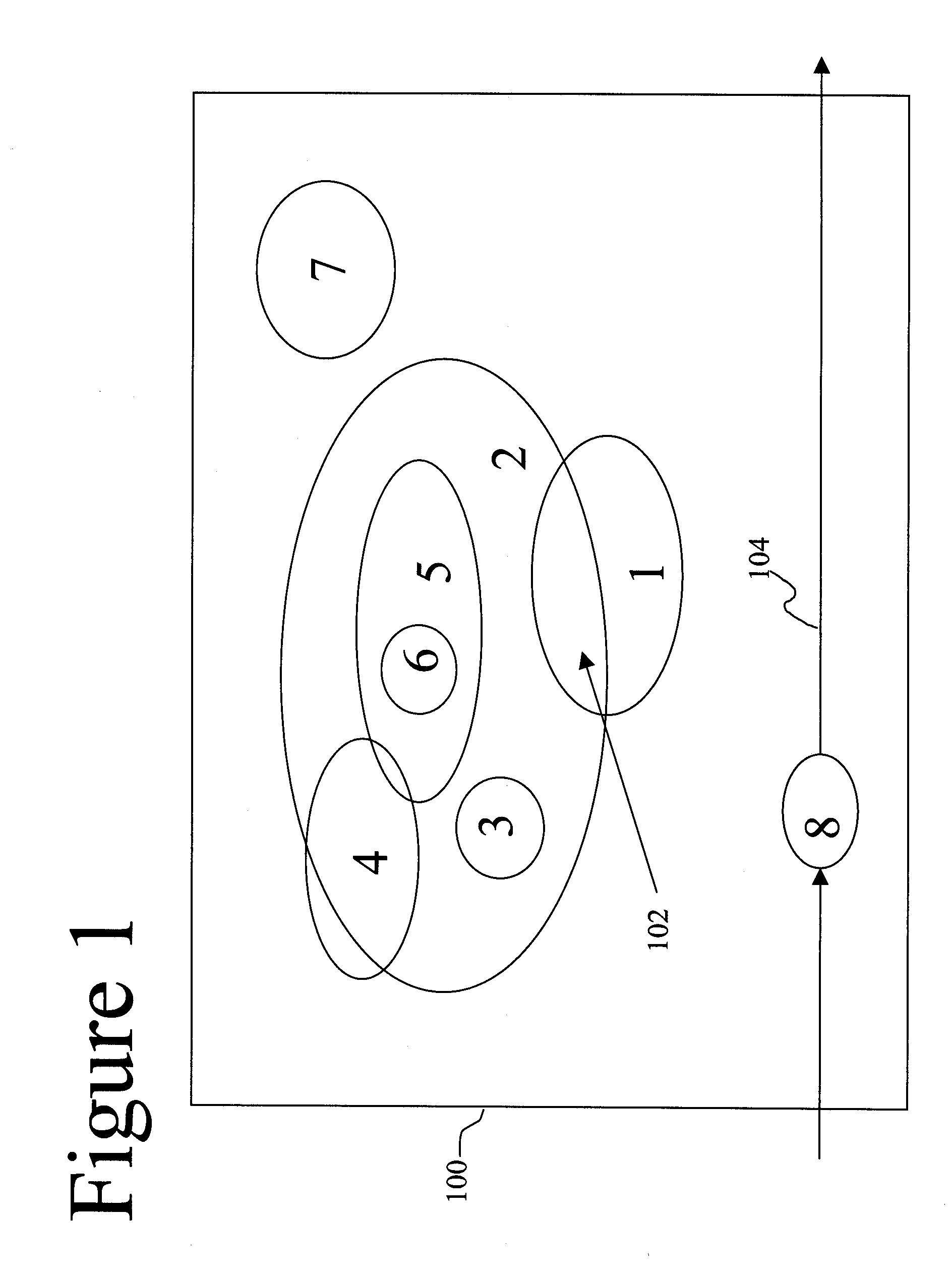
[0017] With reference now to the figures and in particular to FIG. 1, there is depicted a block diagram of a Device Under Test (DUT) 100. DUT 100 is a software model, built with a Hardware Descriptor Language (HDL) synthesis tool, having multiple logic areas 1-8, also known as “logic states.” As illustrated, logic areas 1 and 2 have an overlap 102, which is a logical overlap of function or interrelationship, and / or a physical overlap according to the ultimate physical proximity between two logic areas on a physical chip being modeled by a Hardware Descriptor Language (HDL). If overlap 102 is a logical overlap, then a process performed in logic area 1 directly affects logic are 2, such as providing a branch node, calculation result, decision step, etc. While logic areas 3-6 are not directly affected by logic area 1, logic areas 3-6 are indirectly affected by logic area 1 since logic areas 3-6 are directly affected by logic area 2.

[0018] Logic area 7 is not affected, either directly ...


PUM


Abstract

A method and system for identifying logic function areas, which make up a virtual machine, that are affected by specific testcases. A Hardware Descriptor Language (HDL) is used to create a software model of the virtual machine. A simulator compiles and analyzes the HDL model, and creates a matrix scoreboard identifying logic function areas in the virtual machine. A complete list of testcases is run on the virtual machine while a monitor correlates each testcase with affected logic function areas to fill in the matrix scoreboard. When a subsequent test failure occurs, either because of a modification to a logic function area, or the execution of a new test, all logic function areas that are affected, either directly or indirectly, are identified.

Description

BACKGROUND OF INVENTION [0001] 1. Technical Field [0002] The present invention relates in general to the field of logic design testing, and in particular to the accurately defined logic areas in the logic design. Still more particularly, the present invention relates to a method and system for associating specific logic areas with specific tests, such that a change in the specific logic area or a change in the test will require re-testing only affected logic areas. [0003] 2. Description of the Related Art [0004] Building computer logic takes many steps before the computer logic is physically manufactured. The logic designer typically uses synthesis tools, known as Hardware Descriptor Languages (HDLs), to describe, design and document electronic circuits, as well as simulating faults, in software simulations of hardware. Examples of HDLs are Verilog® and VHDL (Very-high-speed-integrated-circuit Hardware Descriptor Language) for Very Large Scale Integrated Circuits (VLSICs); and Regis...

Claims


Application Information

Patent Timeline
Patent Type & Authority Applications(United States)
IPC IPC(8): G01R31/14G06F11/26
CPCG06F11/261
Inventor NORMAN, JASON MICHAELPRATT, NANCY H.VENTRONE, SEBASTIAN T.
Owner IBM CORP
Why Eureka
Try Eureka