Display apparatus and display controller
- Summary
- Abstract
- Description
- Claims
- Application Information
AI Technical Summary
Benefits of technology
Problems solved by technology
Method used
Image

Examples
first embodiment
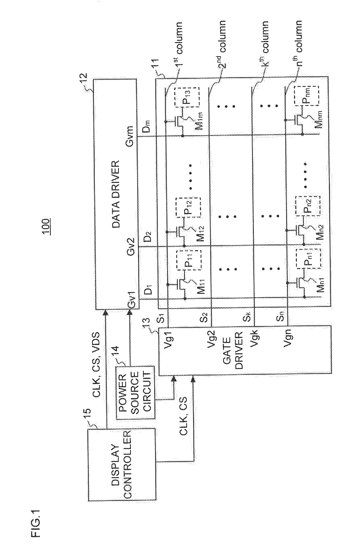
[0030]FIG. 1 is a block diagram illustrating a configuration of a display apparatus 100 according to the present embodiment. An example of the display apparatus 100 is a liquid crystal display apparatus employing an active matrix driving scheme. The display apparatus 100 includes a display panel 11, a data driver 12, a gate driver 13, a power source circuit 14, and a display controller 15.
[0031]The display panel 11 includes a semiconductor substrate on which a plurality of pixel units P11 to Pnm and a plurality of pixel switches M11 to Mnm (n, m: a natural number larger than or equal to two) are arranged in a matrix shape. The display panel 11 includes n scanning lines S1 to Sn and m data lines D1 to Dm disposed so as to intersect with the scanning lines S1 to Sn. The pixel units P11 to Pnm and the pixel switches M11 to Mnm are provided at intersections between the scanning lines S1 to Sn and the data lines D1 to Dm.
[0032]The pixel switches M11 to Mnm are controlled to be ON or OFF ...
second embodiment
[0072]A display apparatus of the second embodiment differs from the display apparatus 100 of the first embodiment in that a timing difference between a selection period of each of scanning pulse signals Vg1 to Vgn and one data period of gradation voltage signals Gv1 to Gvm is adjusted.
[0073]A display controller 15 of the present embodiment controls a data driver 12 and a gate driver 13 so as to adjust a timing difference dh2 between a selection period of the scanning pulse signals Vg1 to Vgn and one data period of the gradation voltage signals Gv1 to Gvm.
[0074]Specifically, the display controller 15 controls timing for an operation of providing the gradation voltage signals Gv1 to Gvm by the data driver 12 and an operation of providing the scanning pulse signals Vg1 to Vgn by the gate driver 13. This adjusts the timing difference dh2 to be smaller on the side closer to the gate driver 13 (hereinafter, referred to as a scanning line near end) and to be larger on the side farther away...
third embodiment
[0079]A display apparatus of the present embodiment differs from the display apparatus 100 of the first embodiment in that a selection period of each of scanning pulse signals Vg1 to Vgn and one data period of gradation voltage signals Gv1 to Gvm have lengths different from each other.
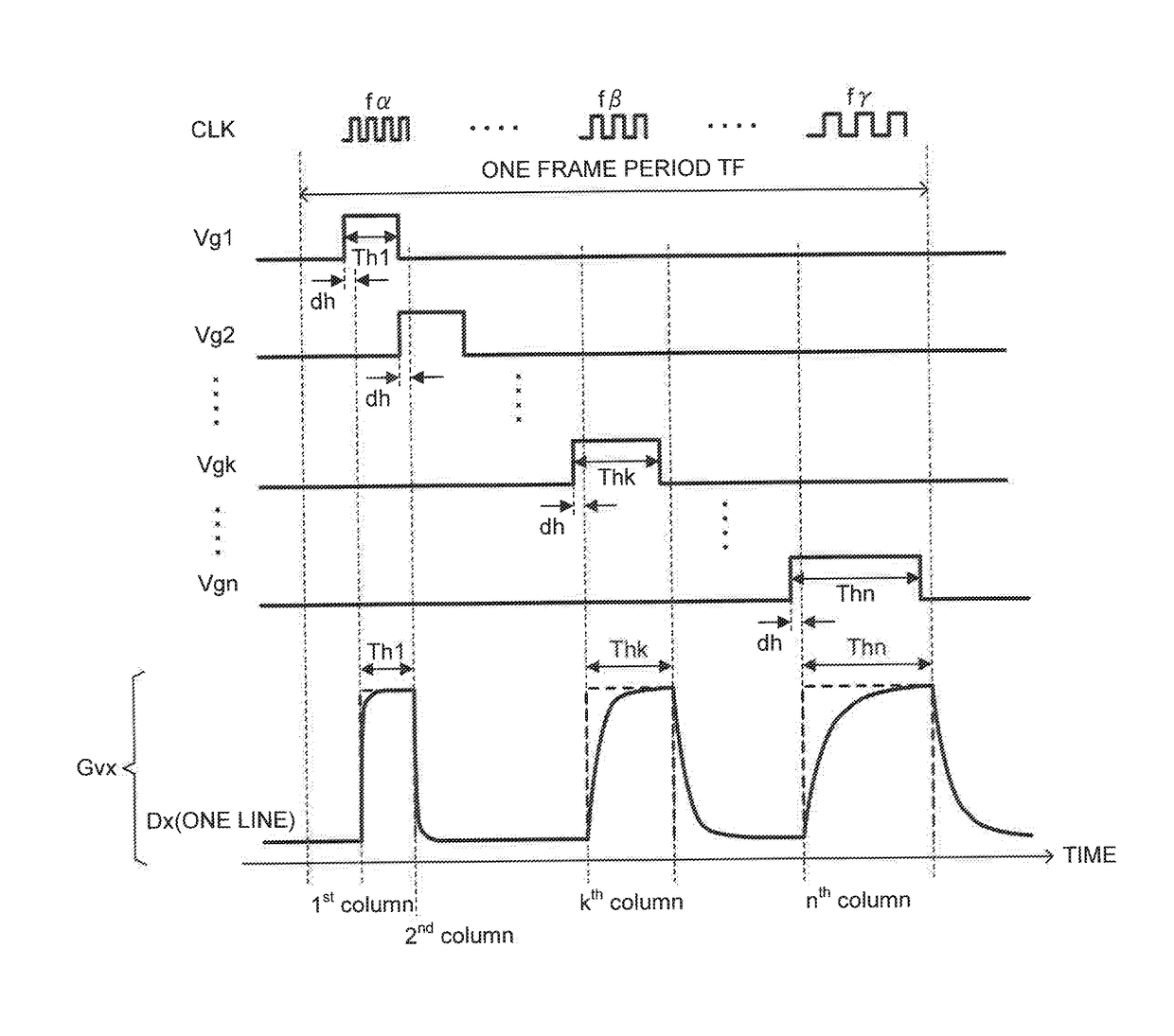
[0080]FIG. 11 is a time chart showing a modulated clock signal CLK in one frame period TF, the scanning pulse signals Vg1 to Vgn, and a gradation voltage signal Gvx provided to a data line Dx in the display apparatus of the present embodiment. Here, it is assumed that the display apparatus of the present embodiment is driven by a column inversion driving scheme and every gradation voltage signal Gvx in one frame has the same polarity.
[0081]A gate driver 13 of the present embodiment generates the scanning pulse signals Vg1 to Vgn each having a pulse width corresponding to the sum of the data period of a gradation voltage signal Gvx provided to one of pixel units P11 to Pnm and the data period of a grada...
PUM
 Abstract
Description
Claims
Application Information
 - R&D
- Intellectual Property
- Life Sciences
- Materials
- Tech Scout
- Unparalleled Data Quality
- Higher Quality Content
- 60% Fewer Hallucinations
Browse by: Latest US Patents, China's latest patents, Technical Efficacy Thesaurus, Application Domain, Technology Topic, Popular Technical Reports.
© 2025 PatSnap. All rights reserved.Legal|Privacy policy|Modern Slavery Act Transparency Statement|Sitemap|About US| Contact US: help@patsnap.com