

Relay cooling device
a relay and cooling device technology, applied in relays, contact heating/cooling, transportation and packaging, etc., can solve the problems of increasing the size of the relay, increasing and not being practical, so as to reduce the manufacturing cost of the relay and facilitate the cooling effect of the relay
- Summary
- Abstract
- Description
- Claims
- Application Information
AI Technical Summary
Benefits of technology
Problems solved by technology
Method used
Image

Examples
first embodiment
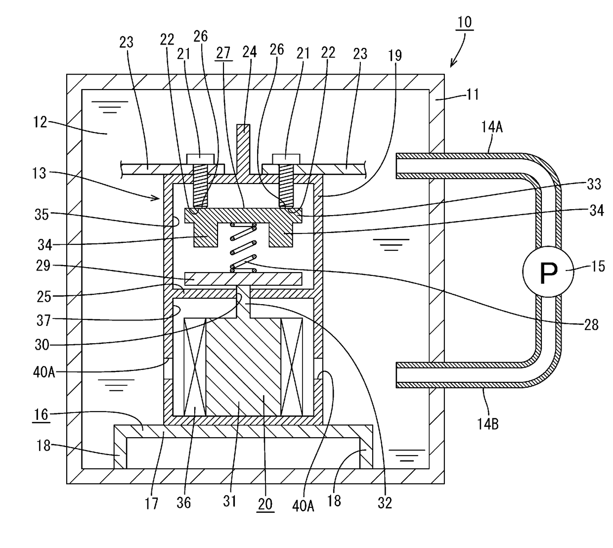
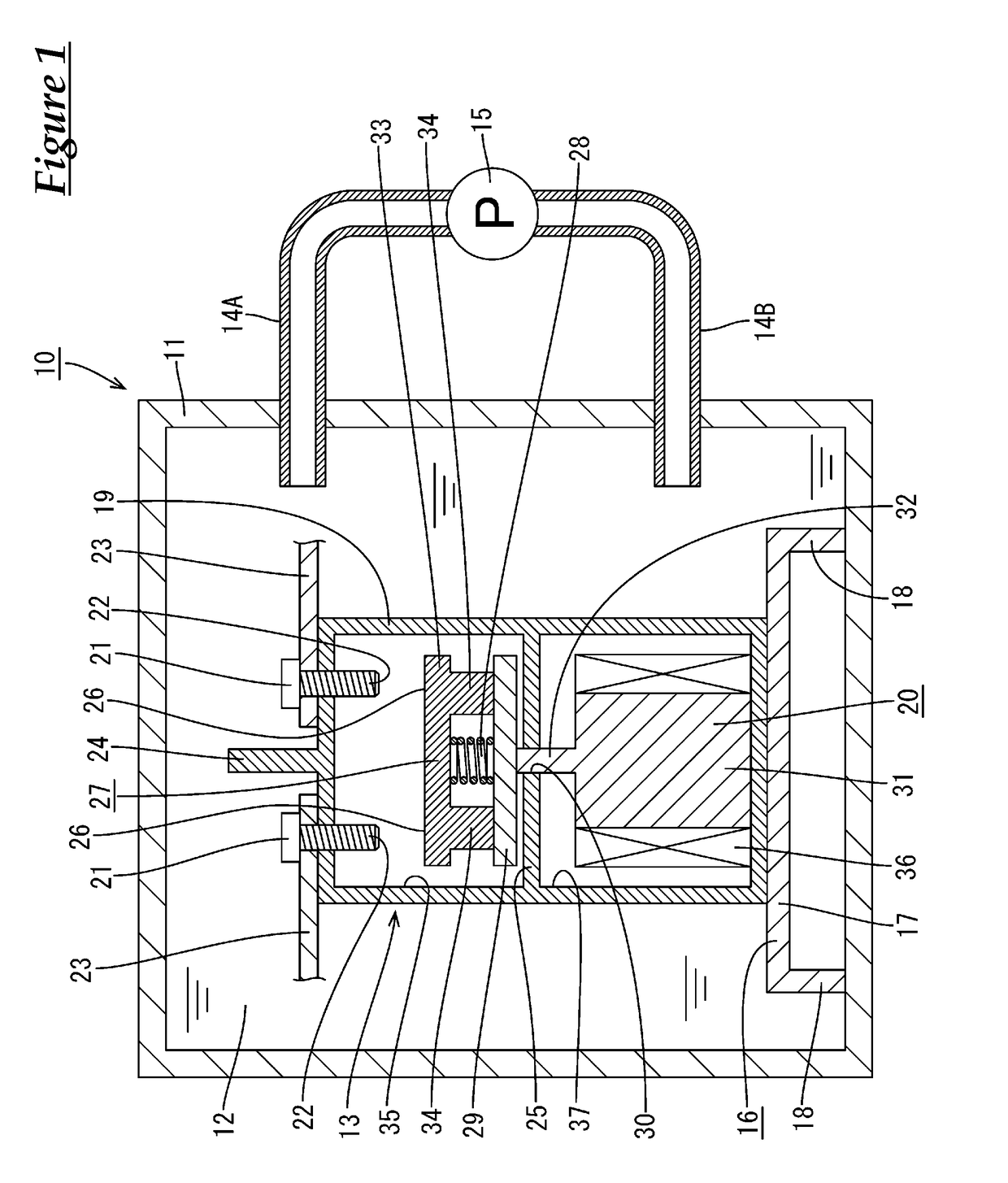
[0033]A first embodiment of technology disclosed in the present specification will be described below with reference to FIGS. 1 and 2. A relay cooling device 10 according to the present embodiment has a container 11, a liquid coolant 12 that is stored in the container 11, and a relay 13 that is immersed in the liquid coolant 12. Note that the terms upper and lower in the following description are respectively based on the upper side and the lower side in FIG. 1. Also, the terms right and left in the description are respectively based on the right side and the left side in FIG. 1.
[0034]The container 11 may be made of a metal, or may be made of a synthetic resin, and any material can be appropriately selected and used as necessary. The container 11 is sealed. The liquid coolant 12 is stored in the container 11. Two pipes 14A and 14B are attached to a side wall of the container 11 so as to be side-by-side in the vertical direction. A left end portion of the upper pipe 14A penetrates to...
embodiment
Actions and Effects of Embodiment
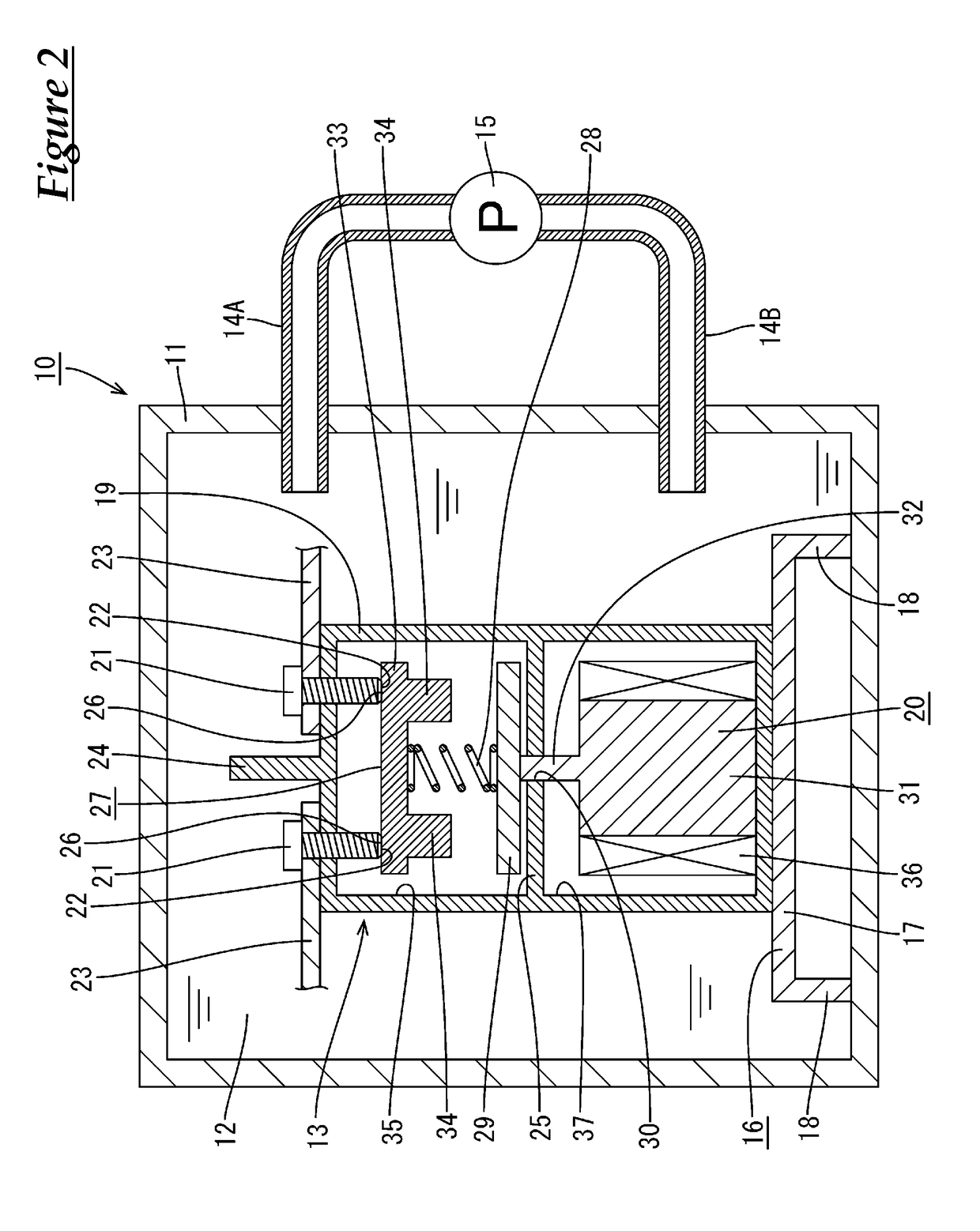
[0051]Next, actions and effects of the present embodiment will be described. According to the present embodiment, the relay cooling device 10 includes the container 11, the liquid coolant 12 that is stored in the container 11, and the relay 13 that is immersed in the liquid coolant 12. Accordingly, while current flows between the two bus bars 23, heat that is generated by the fixed contacts 22 and the movable member 27 is transmitted to the liquid coolant 12 via the wall portions of the case 19 and the fixed terminals 21 that project from the case 19. Accordingly, it is possible to improve the relay 13 cooling efficiency.
[0052]As a result, the accumulation of heat inside the case 19 is suppressed, thus suppressing a rise in the temperature inside the case 19. Accordingly, an excessive rise in the temperature inside the case 19 can be suppressed without increasing the size of the fixed terminals 21 and the movable member 27, and therefore it is possib...
second embodiment
[0056]Next, a second embodiment of technology disclosed in the present specification will be described below with reference to FIG. 3. In the present embodiment, the case 19 of the relay 13 is provided with through-holes 40A in wall portions that constitute the coil housing chamber 37. In the present embodiment, the through-holes 40A are formed in the walls on the left and right sides in FIG. 3. Accordingly, the liquid coolant 12 flows into and out from the coil housing chamber 37.
[0057]Configurations other than those described above are substantially the same as in the first embodiment, and therefore like members are denoted by like reference signs, and redundant descriptions will not be given.
[0058]According to the above configuration, the liquid coolant 12 can come into direct contact with the coil 36 and a core 31. Accordingly, heat generated by the fixed terminals 21 and the movable member 27 is transmitted to a core 31 and the coil 36 via the magnetic member 29 and the project...
PUM
 Abstract
Description
Claims
Application Information