Pattern generator circuit for high-speed pulse generation

a pulse generation and pattern technology, applied in the field of high-speed pulse generation, can solve the problems of value information loss, frame rate limitation by the speed with which pixels can be read, etc., and achieve the effect of short integration times and better tradeoffs between spatial and temporal resolution

Active Publication Date: 2018-11-15
NAT TECH & ENG SOLUTIONS OF SANDIA LLC
View PDF4 Cites 3 Cited by
  • Summary
  • Abstract
  • Description
  • Claims
  • Application Information

AI Technical Summary

Benefits of technology

[0011]We have developed a high-speed CMOS camera with extremely short integration times and interframe times. Our new camera design has implementations as a framing camera and implementations as a streak camera. Various improved features have made it possible for our new camera to achieve better tradeoffs between spatial and temporal resolution than those heretofore available.

Problems solved by technology

This method provides very fast read-out, but valuable information may be lost when imaging an object that is changing rapidly.
However, the frame rate is limited by the speed with which the pixels can be read out and digitized.

Method used


Image

  • Pattern generator circuit for high-speed pulse generation
  • Pattern generator circuit for high-speed pulse generation
  • Pattern generator circuit for high-speed pulse generation

Examples


Embodiment Construction

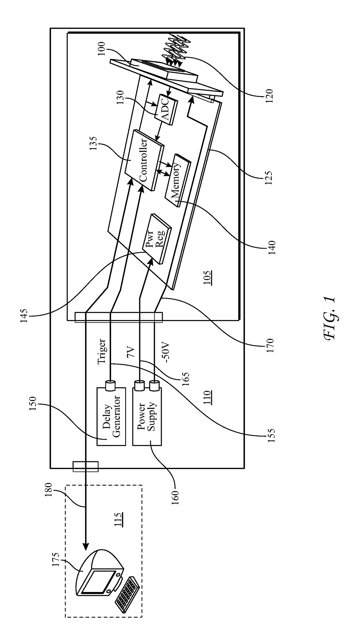
[0033]FIG. 1 is a block diagram of a typical experimental arrangement in which a CMOS camera 100 in a laboratory chamber 105 is supported by circuitry in an antechamber 110 and remotely controlled from a control room 115. As seen in the drawing, the camera is being impinged by a burst 120 of radiation, for example x-radiation, that contains the image information. A printed wiring board (PWB) 125 within chamber 105 contains an analog-to-digital converter (ADC) 130 which receives and processes data signals from the camera. The PWB also contains a local controller 135, a local memory 140, and a power regulator 145.

[0034]Within the antechamber 110, there is seen a delay generator 150 connected to the local controller on the PWB over trigger line 155. Also seen within the antechamber is power supply 160. In the figure, the power supply is shown as having a 7-volt output, which is delivered to the power regulator on the PWB over low-voltage line 165. The power supply is further shown as h...


PUM


Abstract

A pattern generator circuit includes a high-speed shift register and a non-overlap generator. The shift register is programmable to produce a pulse train of pulses having a defined pulse duration and a defined pulse-to-pulse interval. The non-overlap generator deserializes the incoming pulse train, and it produces a time-separated reset pulse based on the pulse train. The shift register is configured to permit the pulse durations and pulse-to-pulse interval to be selected arbitrarily over specified ranges in increments of a basic time unit that depends on the oscillator period.

Description

CROSS-REFERENCE TO RELATED APPLICATION[0001]This application is a divisional of prior U.S. patent application Ser. No. 15 / 234,636, filed Aug. 11, 2016 under the title, “High-Speed CMOS Camera”, which is commonly owned herewith and the entirety of which is hereby incorporated herein by reference.STATEMENT OF GOVERNMENT INTEREST[0002]This invention was made with Government support under Contract No. DE-AC04-94AL85000 awarded by the U.S. Department of Energy. The Government has certain rights in the invention.FIELD OF THE INVENTION[0003]The invention relates to high-speed pulse generation for electronic imaging devices and other applications.ART BACKGROUND[0004]The discipline of high-speed imaging has found many applications in medicine, science, engineering, and other fields. The advent of electronic image sensors such as focal plane arrays (FPAs) based on silicon photodiode sensors has extended the usefulness of this discipline by extending the available time resolutions far into the...

Claims


Application Information

Patent Timeline
Patent Type & Authority Applications(United States)
IPC IPC(8): H04N5/374H01L27/146H04N5/378
CPCH01L27/14634H01L27/14636H04N5/374H04N5/378H01L27/14643H04N25/771H04N25/745H04N25/76
Inventor SANCHEZ, MARCOS O.CLAUS, LIAM D.ROBERTSON, GIDEONPEARSON, SEANMONTOYA, ANDREW
Owner NAT TECH & ENG SOLUTIONS OF SANDIA LLC
Why Eureka
Try Eureka