
Breach Detection Glove with a High Contrast Between the Color on the Donning Side and the Grip Side of the Glove

Active Publication Date: 2018-11-22
O&M HALYARD INC +3
View PDF5 Cites 6 Cited by
  • Summary
  • Abstract
  • Description
  • Claims
  • Application Information

AI Technical Summary

Benefits of technology

The patent text describes a technology where a breach in a layer can be detected because it will expose the color pigments of another layer. The technical effect of this technology is that it can help in identifying the source of the breach and taking necessary measures to prevent it.

Problems solved by technology

Whether being used in a medical or manufacturing setting, there is a risk that the gloves could become punctured during use, such as when the gloves are used around sharps such as needles, scissors, blades, hemostats, etc. or equipment used in manufacturing.
When such a puncture occurs, the protective barrier provided by the gloves is breached, and the wearer has an increased risk of exposure to bacteria, viruses, pathogens, infections, diseases, etc.
Further, depending on the environment in which the glove is being used, other factors may make the breach difficult to see.
For example, the lighting may be poor, or the glove may be soiled or otherwise altered in appearance, making a small puncture nearly impossible to see.
However, it has not been feasible to form a colored layer where the color is even, uniform, and not muddied with pigment while at the same time achieving suitable saturation and value without a “bleed out” effect unless the other layer is white.
In addition, because one of the layers is white, breach detection is difficult, particularly in industrial and manufacturing settings, where the wearer of the glove may come in contact with many hazardous materials.
Thus, the wearer might not be aware or alerted to the fact that the glove has been breached upon seeing a whitish color present on the glove.
Further, the environment surrounding the wearer may include walls, countertops, equipment, lighting, etc. that are white in color or that accentuate a white color, making it difficult for the wearer to discern a visual cue on a white glove.

Method used


Image

  • Breach Detection Glove with a High Contrast Between the Color on the Donning Side and the Grip Side of the Glove
  • Breach Detection Glove with a High Contrast Between the Color on the Donning Side and the Grip Side of the Glove
  • Breach Detection Glove with a High Contrast Between the Color on the Donning Side and the Grip Side of the Glove

Examples


example 1

[0114]In Example 1, elastomeric gloves were made using a polyurethane formulation and a nitrile rubber formulation via the 4-step coagulant dip-coating process described above and then subjected to mechanical testing. The polyurethane and nitrile rubber formulations utilized are described in more detail in Tables 2 and 3 below. The first coagulant dip (the dip step prior to the polyurethane dip) included 12 wt. % calcium nitrate, while the second coagulant dip (the dip step after the polyurethane dip and before the nitrile rubber dip) included 18 wt. % calcium nitrate. Gloves were formed so that the nitrile rubber layer extended past the polyurethane layer to form a cuff, and their mechanical properties were compared to conventional purple nitrile gloves. The tensile testing parameters and methods are defined in American Society for Testing and Materials (ASTM) test standard D-412-98a. In the present invention, the ASTM protocol was employed with no changes. The testing apparatus us...

example 2

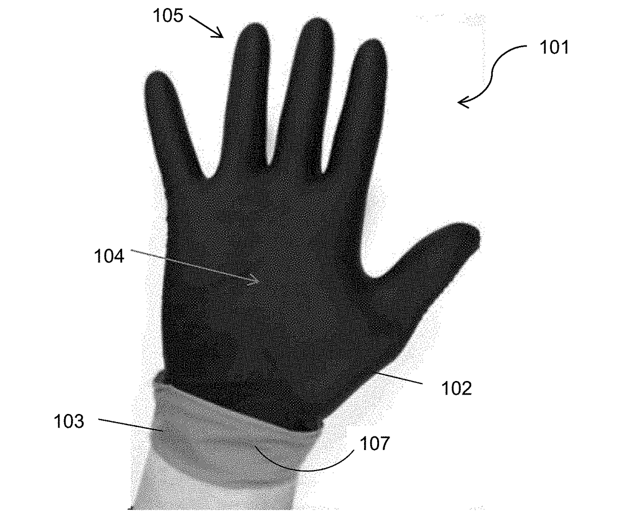
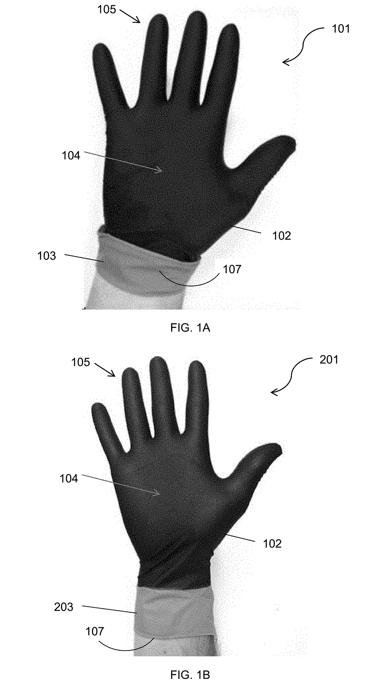
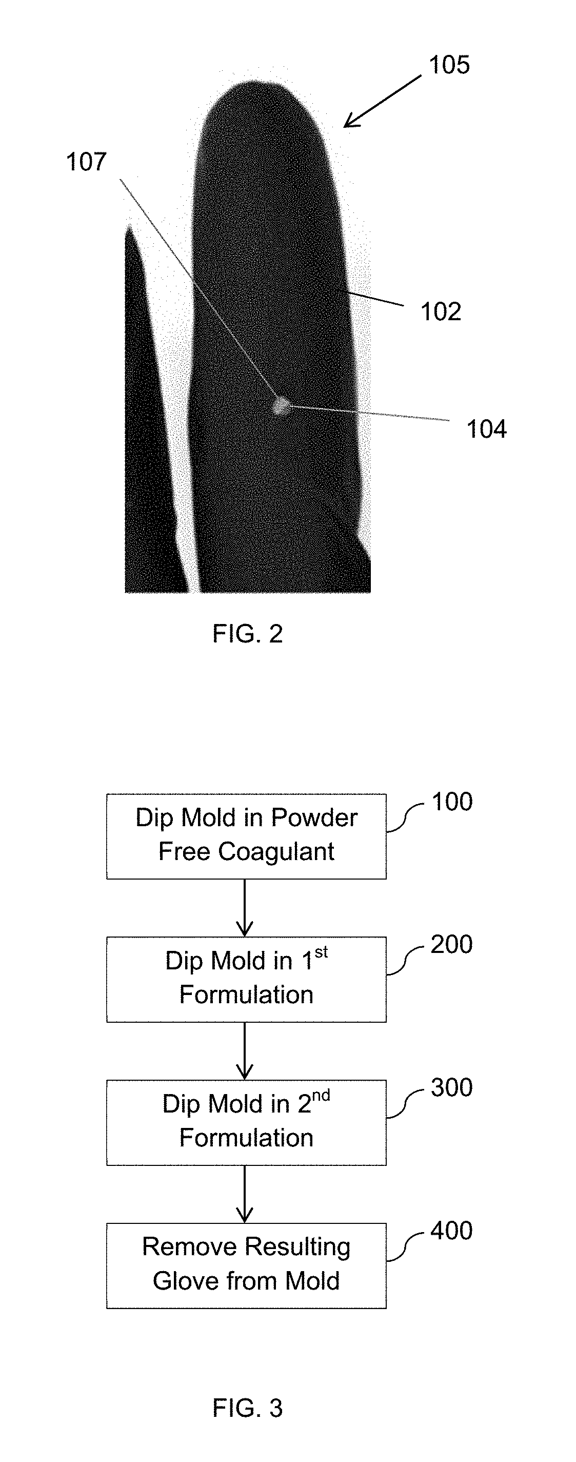
[0116]In Example 2, the ability to form a multilayered glove from a four-dip process having a black pigment grip side layer and an orange pigment donning side layer was demonstrated. A glove mold was first dipped in a first powder free coagulant containing 10 wt. % calcium nitrate. The mold was then dipped in a first nitrile rubber formulation containing 1 part of black pigment per 100 parts of nitrile rubber to form the grip side layer, where the grip side layer had a total solids content of 20%. Then, the mold was dipped in a second powder free coagulant containing 18 wt. % calcium nitrate. Thereafter, the mold was dipped in a second nitrile rubber formulation containing 10 parts titanium dioxide and 5 parts orange pigment per 100 parts of nitrile rubber to form the donning side layer, where the layer had a total solids content of 20%. The mold was dipped to the same level for both nitrile rubber formulations, then the cuff region of the glove was folded over after its removal fro...

example 3

[0117]In Example 3, the ability to form a multilayered glove from a three-dip process having a black pigment grip side layer and an orange pigment donning side layer was demonstrated. A glove mold was first dipped in a first powder free coagulant containing 18 wt. % calcium nitrate. The mold was then dipped in a first nitrile rubber formulation containing 1 part of black pigment per 100 parts of nitrile rubber to form the grip side layer, where the grip side layer had a total solids content of 20%. Thereafter, the mold was dipped in a second nitrile rubber formulation containing 10 parts titanium dioxide and 5 parts orange pigment per 100 parts of nitrile rubber to form the donning side layer, where the layer had a total solids content of 20%. The mold was dipped to the same level for both nitrile rubber formulations, then the cuff region of the glove was folded over after its removal from the mold to expose the lighter donning side layer at the cuff. Due at least in part to the lig...


PUM

PropertyMeasurementUnit
Fractionaaaaaaaaaa
Fractionaaaaaaaaaa
Fractionaaaaaaaaaa

Abstract

Elastomeric articles, such as gloves, made from more than one layer, are provided. The gloves can include a first (grip side) layer in which a first colorant is compounded or integrated and a second (donning side) layer in which a second colorant is compounded or integrated. Alternatively, the gloves can include a translucent first layer and a second layer in which a colorant is compounded or integrated. Either arrangement can enable a breach of the first layer to be more easily detected, either due to the high level of contrast between the first layer and the second when a first colorant and a second colorant are utilized, or due to the translucence of the first layer as compared to the donning side layer, where the intensity of the second layer is increased upon a breach of the translucent first layer.

Description

RELATED APPLICATIONS[0001]The present invention claims priority to U.S. Provisional Application No. 62 / 257,276, filed on Nov. 19, 2015, which is incorporated herein in its entirety by reference thereto.FIELD OF THE INVENTION[0002]The present invention relates to elastomeric articles that are made from more than one layer of material. In particular, the invention pertains to any elastomeric glove (e.g., surgical, exam, industrial, emergency responder, etc.) containing at least two separate layers of elastomeric materials.BACKGROUND OF THE INVENTION[0003]The development of modern rubber materials has made possible the manufacture of a wide range of elastomeric articles, such as gloves, having varying properties of strength and chemical resistance. Gloves are used as an infection protection device to protect the wearer from exposure to bacteria, viruses, pathogens, infections, diseases, etc. that could transfer from a surface or bodily fluid (e.g., blood) to the wearer's skin. Gloves a...

Claims


Application Information

Patent Timeline
IPC IPC(8): A41D19/00B32B25/04B29C41/00B29C41/14B29C41/22B32B25/08B32B27/40
CPCA41D19/0082A41D19/0006B32B25/042B29C41/003B29C41/14B29C41/22B32B25/08B32B27/40A41D2400/44B32B2307/402B32B2437/02B29K2105/0032B29K2019/00B29K2075/00B29L2031/4864B29L2009/00A61B42/30A61B42/10
Inventor MODHA, SHANTILAL H.ROBERT, PATRICK H.ISSARA, SOPHAZAKARIA, ZAMSARI
Owner O&M HALYARD INC
Learn More