Multi-station wheel burr removing device

a technology of wheel burrs and removal devices, which is applied in the direction of grinding drives, grinding feeders, manufacturing tools, etc., can solve the problems of low efficiency, time and labor waste, and the method does not adapt to large-batch production at all, so as to achieve high automation and high production efficiency. , the effect of advanced process

Active Publication Date: 2018-11-22
CITIC DICASTAL
View PDF0 Cites 8 Cited by
  • Summary
  • Abstract
  • Description
  • Claims
  • Application Information

AI Technical Summary

Benefits of technology

[0012]The multi-station wheel burr removing device of the present application may be used for not only removing burrs at the edge of the wheel flange, but also removing burrs at the wheel valve hole, so the production efficiency is very high; and simultaneously, the device has the characteristics of high automation degree, advanced process, strong generality and high safety and stability.

Problems solved by technology

In the machining production process of an aluminum alloy wheel, a flange is machined on a lathe, burrs may be produced at the edge of the machined flange, and the burrs are removed by an operator holding a burr removing knife in the traditional manner, so that the efficiency is very low and the method does not adapt to large-batch production at all.
Furthermore, a wheel valve hole is formed by drilling, and burrs are also produced at its edge and removed manually, so that time and labor are wasted.

Method used


Image

  • Multi-station wheel burr removing device
  • Multi-station wheel burr removing device
  • Multi-station wheel burr removing device

Examples


Embodiment Construction

[0017]The details and working conditions of the specific device provided by the present application will be described in combination with the accompanying drawings.

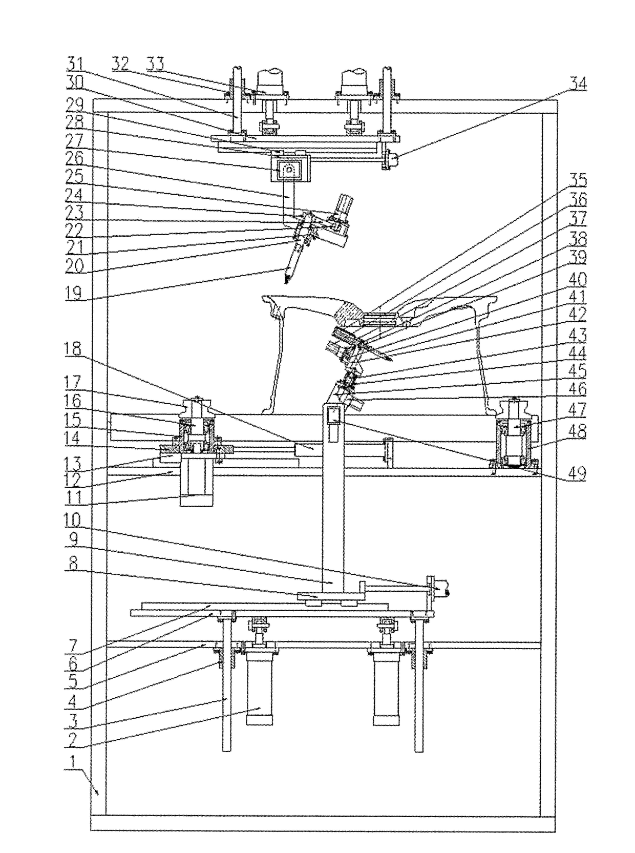
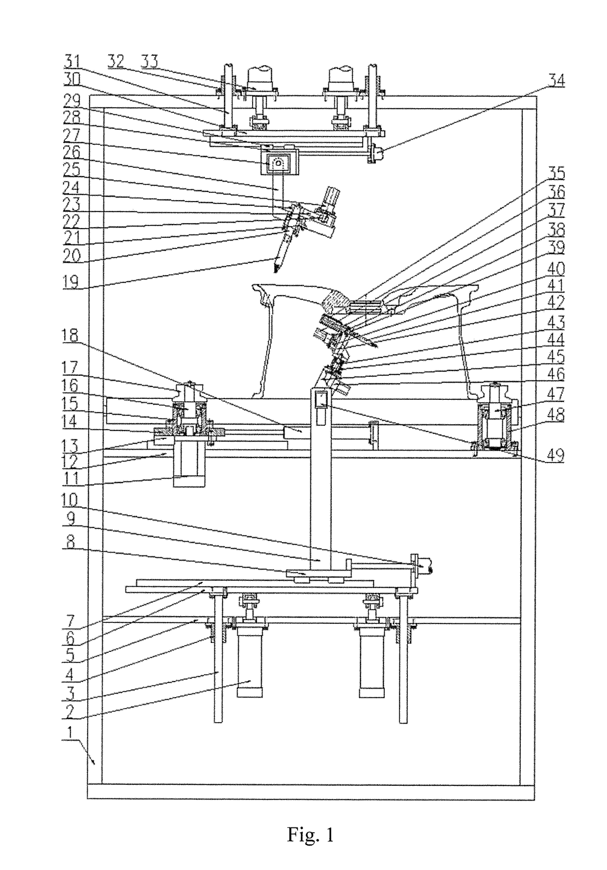
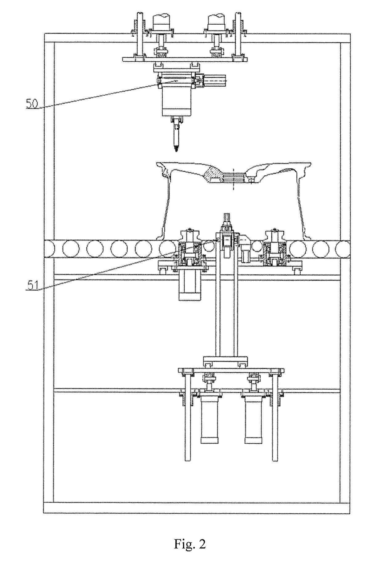
[0018]The device comprises a frame 1, cylinders I 2, lower guide posts 3, lower guide sleeves 4, a lower fixed plate 5, a lower lifting plate 6, a guide rail I 7, a lower sliding plate 8, a vertical plate 9, an electric servo cylinder I 10, a servo motor I 11, an upper fixed plate 12, a guide rail II 13, a left sliding plate 14, left bearing seats 15, left shafts 16, V-shaped rollers 17, a cylinder II 18, an upper grinding head 19, an upper shaft 20, an upper bearing seat 21, a belt pulley I 22, a synchronous belt I 23, a belt pulley II 24, a servo motor II 25, an upturning plate 26, a servo motor III 27, a sliding rack 28, a guide rail III 29, an upper lifting plate 30, upper guide posts 31, upper guide sleeves 32, cylinders III 33, an electric servo cylinder II 34, a rolling brush 35, a servo motor IV 36, a belt pulley ...


PUM


Abstract

The application discloses a multi-station wheel burr removing device, includes lifting translation systems, a clamping drive system and grinding systems. When the device is used, a cylinder II drives a left sliding plate to move right so that four V-shaped rollers clamp a wheel, and a servo motor I drives the clamped wheel to rotate; a servo motor VI adjusts the angle of a rolling brush, an electric servo cylinder I adjusts the position of the rolling brush; cylinders I drive the rolling brush to ascend; a servo motor III adjusts the angle of the upper grinding head, an electric servo cylinder II adjusts the position of the upper grinding head, and cylinders III drive the upper grinding head to descend.

Description

CROSS-REFERENCE TO RELATED APPLICATIONS[0001]This application claims priority to Chinese Patent Application No. 2017103569997, filed on May 19, 2017, which is hereby incorporated by reference in its entirety.TECHNICAL FIELD[0002]The present application relates to a wheel surface treatment device, and specifically, to a wheel burr removing device.BACKGROUND ART[0003]In the machining production process of an aluminum alloy wheel, a flange is machined on a lathe, burrs may be produced at the edge of the machined flange, and the burrs are removed by an operator holding a burr removing knife in the traditional manner, so that the efficiency is very low and the method does not adapt to large-batch production at all. Furthermore, a wheel valve hole is formed by drilling, and burrs are also produced at its edge and removed manually, so that time and labor are wasted. Based on said two points, special burr removing equipment for the two positions has been studying all the time in the wheel i...

Claims


Application Information

Patent Timeline
Patent Type & Authority Applications(United States)
IPC IPC(8): B24B5/44B24B47/10
CPCB24B47/10B24B5/44B24B9/04B24B41/00B24B41/005B24B41/02B24B41/06B24B47/12B24B27/0076B24B41/067B24B19/28B24B5/065
Inventor XUE, BOWENWANG, HAIYILI, HUAYOUGUO, JIANDONG
Owner CITIC DICASTAL
Why Eureka
Try Eureka