Efficient HVAC operation by predictive control

a predictive control and hvac technology, applied in the direction of road transportation emission reduction, vehicle heating/cooling devices, vehicle components, etc., can solve the problems of increasing or decreasing the state of charge of batteries, and achieve the effect of reducing total power provided, increasing power, and reducing power

Active Publication Date: 2018-11-22
TOYOTA MOTOR ENGINEERING & MANUFACTURING NORTH AMERICA
View PDF5 Cites 25 Cited by
  • Summary
  • Abstract
  • Description
  • Claims
  • Application Information

AI Technical Summary

Benefits of technology

[0005]Described herein is a system for adjusting a vehicle climate control based on a predicted action of a vehicle. The system includes a power source designed to generate power to propel the vehicle. The system also includes a sensor designed to detect data that is usable to predict an upcoming acceleration or deceleration of the vehicle. The system also includes a heating, ventilation, and air conditioning (HVAC) system having a compressor designed to compress vapor refrigerant and a fan designed to blow conditioned air into a cabin of the vehicle, the compressor and the fan both designed to operate using a portion of the power generated by the power source. The system further includes an electronic control unit (ECU) coupled to the power source, the sensor, and the HVAC system. The ECU is designed to predict that the vehicle will accelerate or decelerate within a predetermined distance or a predetermined amount of time based on the data detected by the sensor. The ECU is further designed to decrease the power that is provided to the compressor and increase the power that is provided to the fan when the ECU predicts that the vehicle will accelerate within the predetermined distance or the predetermined amount of time in order to reduce total power provided to the HVAC system and to reduce variance in total noise and vibration generated by the HVAC system. The ECU is further designed to increase the power that is provided to the compressor when the ECU predicts that the vehicle will decelerate within the predetermined distance or the predetermined amount of time in order to increase the total power provided to the HVAC system.
[0006]Also described is a system for adjusting a vehicle climate control based on a predicted action of a vehicle. The system includes a power source configured to generate power to propel the vehicle. The system also includes a sensor configured to detect data that is usable to predict an upcoming acceleration or deceleration of the vehicle. The system also includes a heating, ventilation, and air conditioning (HVAC) system having a component that utilizes some of the power generated by the power source to increase or decrease a temperature of a cabin of the vehicle. The system also includes an electronic control unit (ECU) coupled to the power source, the sensor, and the HVAC system. The ECU is designed to predict that the vehicle will accelerate or decelerate within a predetermined distance or a predetermined amount of time based on the data detected by the sensor and to decrease the power that is provided to the HVAC system when the ECU predicts that the vehicle will accelerate within the predetermined distance or the predetermined amount of time in order to increase efficiency of the power source. The ECU is also designed to increase the power that is provided to the HVAC system when the ECU predicts that the vehicle will decelerate within the predetermined distance or the predetermined amount of time in order to increase efficiency of the power source.
[0007]Also described is a method for adjusting a vehicle climate control based on a predicted action of a vehicle. The method includes generating, by a power source, power to propel the vehicle. The method further includes detecting, by a sensor, data that is usable to predict an upcoming acceleration or deceleration of the vehicle. The method further includes predicting, by an electronic control unit (ECU), that the vehicle will accelerate or decelerate within a predetermined distance or a predetermined amount of time based on the data detected by the sensor. The method further includes decreasing, by the ECU, the power that is provided to a compressor of a heating, ventilation, and air conditioning (HVAC) system and increasing, by the ECU, the power that is provided to a fan of the HVAC system when the ECU predicts that the vehicle will accelerate within the predetermined distance or the predetermined amount of time in order to reduce total power provided to the HVAC system and to reduce variance in total noise and vibration generated by the HVAC system. The method further includes increasing, by the ECU, the power that is provided to the compressor of the HVAC system and decreasing, by the ECU, the power that is provided to the fan of the HVAC system when the ECU predicts that the vehicle will decelerate within the predetermined distance or the predetermined amount of time in order to increase the total power provided to the HVAC system and to reduce the variance in total noise and vibration generated by the HVAC system.

Problems solved by technology

However, there are times when increasing or decreasing the state of charge of the battery is insufficient to allow the engine to operate at the optimal engine speed and torque.

Method used


Image

  • Efficient HVAC operation by predictive control
  • Efficient HVAC operation by predictive control
  • Efficient HVAC operation by predictive control

Examples


Embodiment Construction

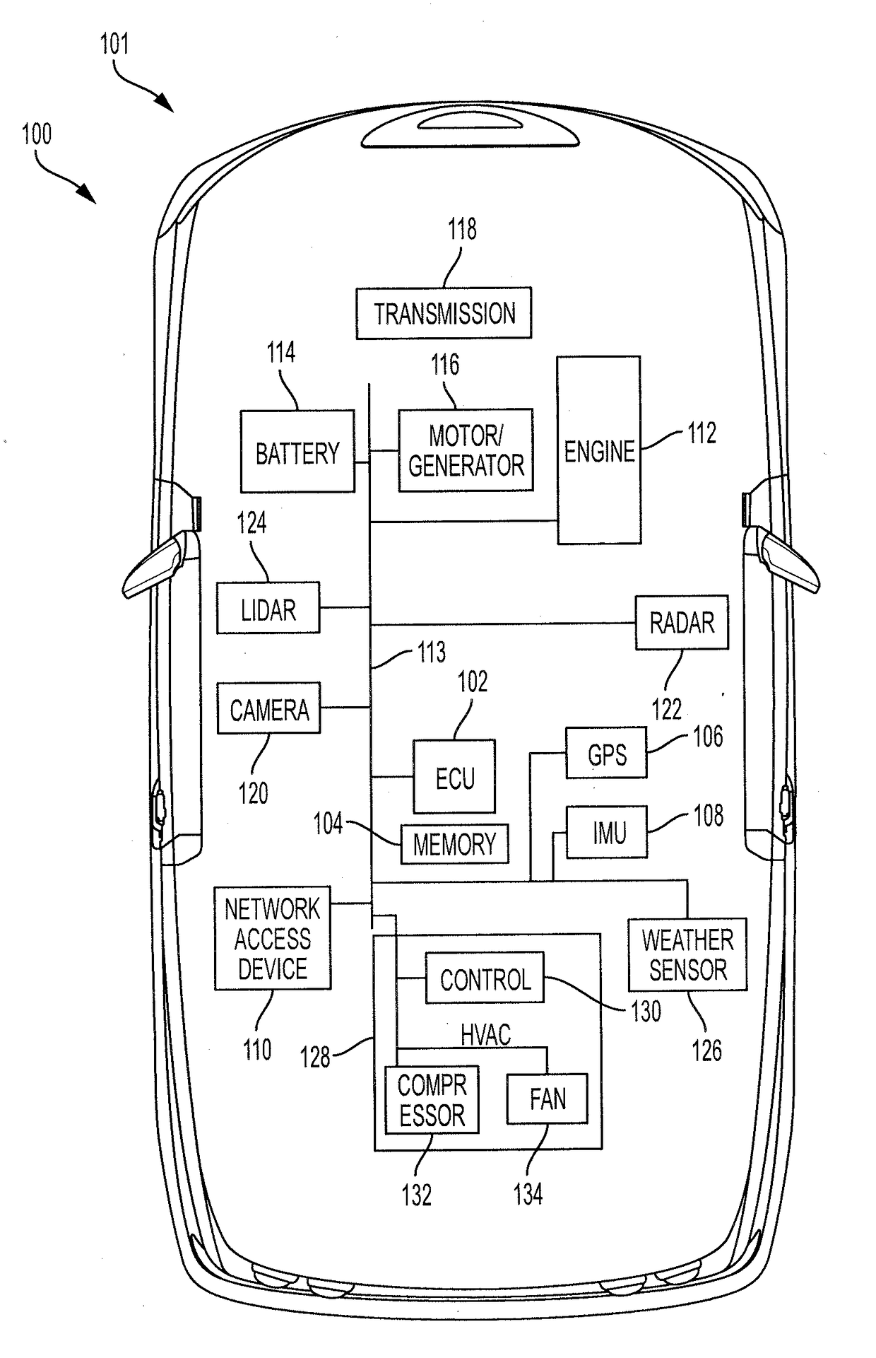
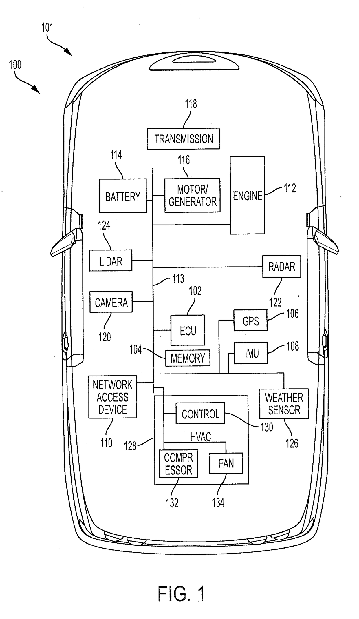
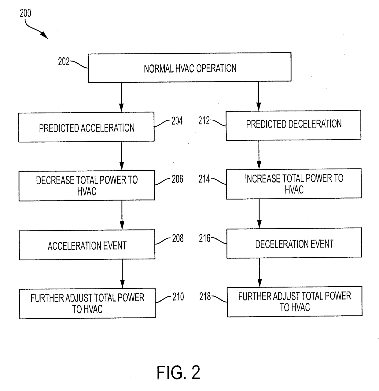
[0013]The present disclosure describes systems and methods for controlling power to a heating, ventilation, and air conditioning (HVAC) system based on predicted accelerations and decelerations of a vehicle. An exemplary system includes a power source, such as one or more of an engine or a motor-generator. The system further includes one or more sensors capable of detecting data that is usable to predict an upcoming acceleration or deceleration. The system further includes a HVAC system that includes a compressor and a fan. The system also includes an electronic control unit (ECU) that can predict whether the vehicle will accelerate or decelerate based on the detected data and that can increase or decrease an amount of power provided to the HVAC system based on the predicted acceleration or deceleration. For example, the ECU may decrease total power provided to the HVAC system to allow more power to be provided for propelling the vehicle in preparation of an upcoming acceleration. T...


PUM


Abstract

A system includes a power source, a sensor to detect data, and a HVAC system having a compressor to compress vapor refrigerant and a fan to blow conditioned air into a cabin of the vehicle, the compressor and the fan both designed to operate using a portion of the power generated by the power source. The system further includes an ECU to predict that the vehicle will accelerate or decelerate based on the data, to decrease power provided to the compressor and increase power provided to the fan when the ECU predicts the acceleration in order to reduce total power provided to the HVAC system and to reduce variance in total noise and vibration generated by the HVAC system, and to increase power to the compressor when the ECU predicts that the vehicle will decelerate in order to increase the total power provided to the HVAC system.

Description

BACKGROUND1. Field[0001]The present disclosure relates to systems and methods for adjusting an amount of power provided to a heating, ventilation, and air conditioning (HVAC) system based on a predicted acceleration or deceleration of the vehicle.2. Description of the Related Art[0002]Electronic control systems for vehicles have been increasing in quantity and improving in quality for years. Such control systems may take actions to increase efficiency of the vehicles for various reasons, such as to save fuel cost for the driver, reduce emissions, and the like. Some of these control systems may learn driver behaviors and may control various features of the vehicle based on the learned driver behaviors. For example, a control system may learn when a vehicle will accelerate or decelerate, may learn rates of acceleration or deceleration, and the like.[0003]Based on the predicted acceleration or deceleration a vehicle may take certain actions to increase vehicle efficiency. For example, ...

Claims


Application Information

Patent Timeline
Patent Type & Authority Applications(United States)
IPC IPC(8): B60H1/00B60H1/32
CPCB60H1/00764B60H1/00428B60H1/00885B60H2001/3273B60H1/3222B60H2001/3266B60H1/3208B60H1/00392Y02T10/88
Inventor GELLER, BENJAMIN M.PAYNE, JOSHUA D.WROBEL, SHANNON ALICIA
Owner TOYOTA MOTOR ENGINEERING & MANUFACTURING NORTH AMERICA
Why Eureka
Try Eureka