Vital sign detection system with random body movement cancellation

Active Publication Date: 2018-11-29
NAT SUN YAT SEN UNIV
View PDF0 Cites 6 Cited by
  • Summary
  • Abstract
  • Description
  • Claims
  • Application Information

AI Technical Summary

Benefits of technology

The present invention is a method for monitoring the vital signs of a person who moves over a large range using a single radar device. It cancels out the effects of body movement by transmitting and retransmitting radar signals through a nonreciprocal network with two antennas. This means that the radar device doesn't have to have high dynamic range to monitor the person's vital signs.

Problems solved by technology

However, the random body movements of the biological subject also cause the Doppler phase shifts in the reflection signal, making the extraction of the vital signs of the biological subject difficult because any slight movements of the body produce large-magnitude Doppler phase shifts that overwhelm those associated with the vital signs.
However, the use of two radar devices increases the complexity of the system and its power consumption.
Moreover, the system can tolerate only small body movements because large body movements commonly generate the nonlinear distortions and so cause great difficulty in extracting the vital signs.
In a word, the prior art is difficult to monitor the vital signs of people who make large body movements.

Method used


Image

  • Vital sign detection system with random body movement cancellation
  • Vital sign detection system with random body movement cancellation
  • Vital sign detection system with random body movement cancellation

Examples


first embodiment

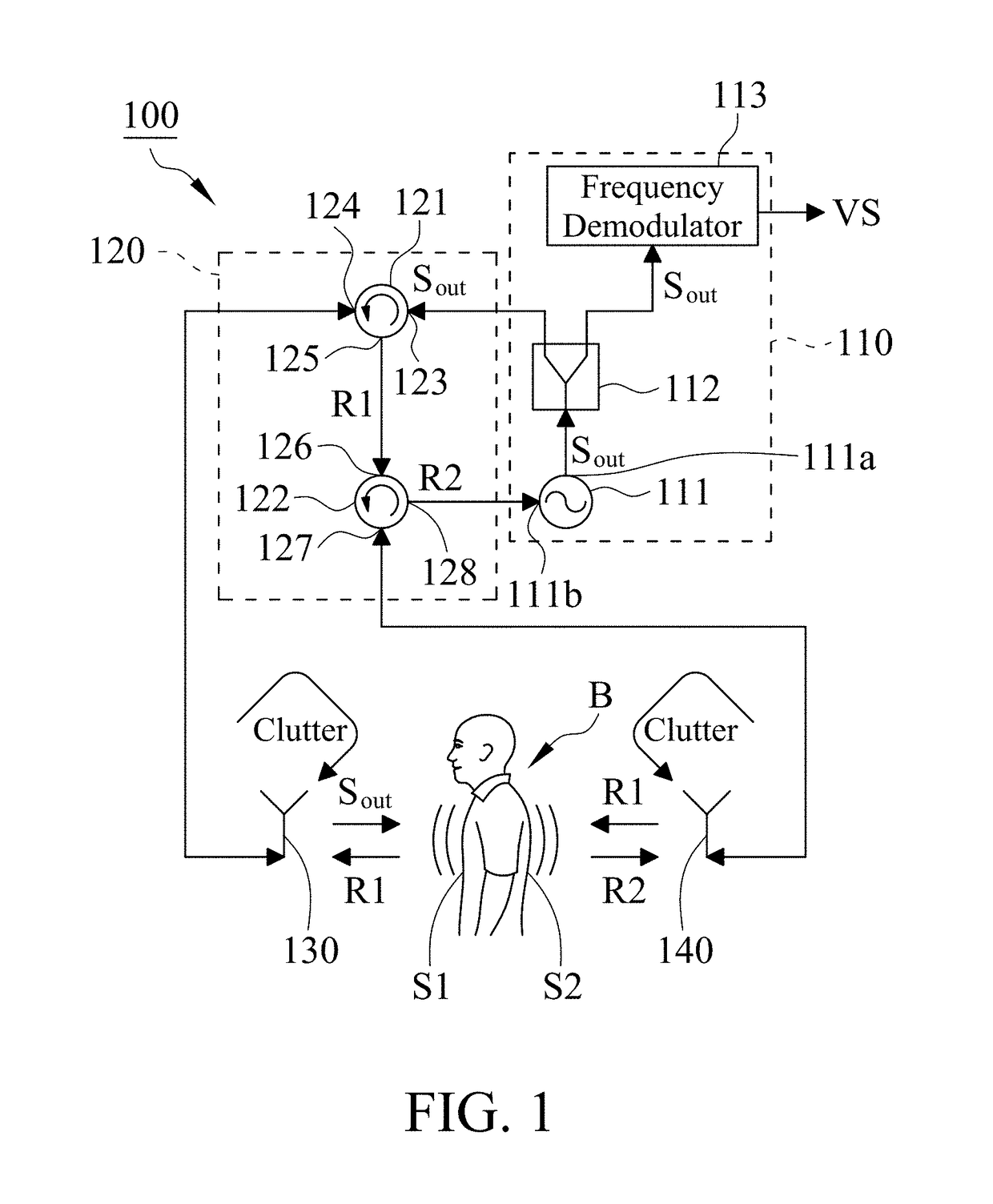
[0012]With reference to FIG. 1, it is a circuit diagram of a vital sign detection system 100 in accordance with the present invention. The vital sign detection system 100 includes a radar device 110, a nonreciprocal network 120, a first antenna 130 and a second antenna 140, wherein the nonreciprocal network 120 is coupled to the radar device 110, the first antenna 130 and the second antenna 140.

[0013]With reference to FIG. 1, the radar device 110 is configured to output an output signal Sout, wherein the radar device 110 may be a pulsed radar, a continuous-wave radar or a self-injection-locked radar. In this embodiment, the radar device 110 is a self-injection-locked radar. The radar device 110 includes an injection-locked oscillator (ILO) 111, a power splitter 112 and a frequency demodulator 113. The ILO 111 includes an output port 111a and an injection port 111b, wherein the output port 111a is configured to output the output signal Sout, and the output frequency of the ILO 111 is...

second embodiment

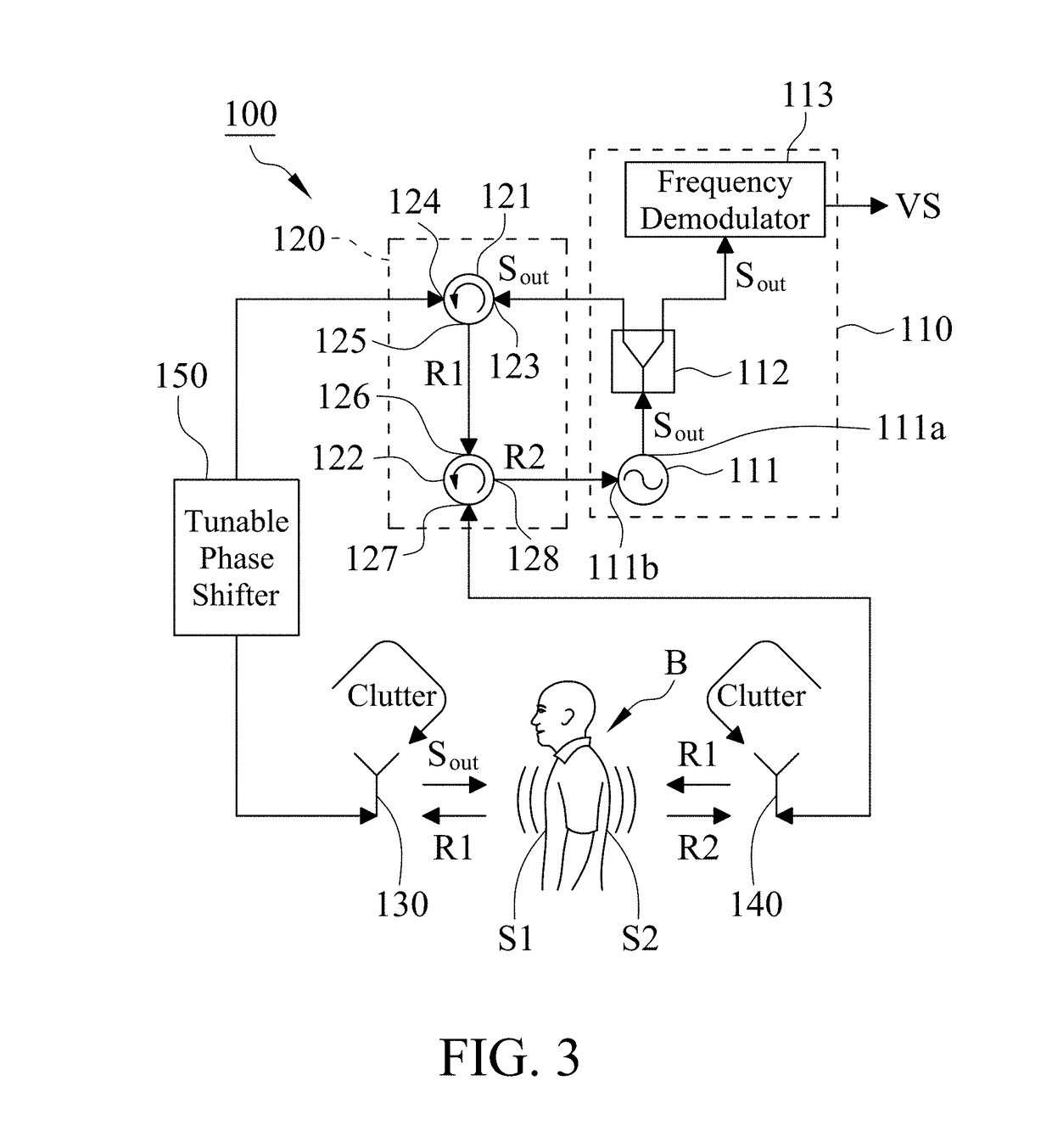
[0022]With reference to FIG. 1, while the first and second antennas 130, 140 respectively receive the first and second reflection signals R1, R2 from the first and second sides S1, S2 of the biological subject B, they also receive the clutter from the environment, which may affect the cancellation of body movements. With reference to FIG. 3, the vital sign detection system 100 of a second embodiment preferably further includes a tunable phase shifter 150 which is coupled with the nonreciprocal network 120 and the first antenna 130. In this embodiment, one end of the tunable phase shifter 150 is electrically connected to the second port 124 of the first circulator 121, and the other end of the tunable phase shifter 150 is electrically connected to the first antenna 130. The tunable phase shifter 150 is configured to adjust the phase of the signals passing through the path between the nonreciprocal network 120 and the first antenna 130 to reduce the clutter effect on the random body m...


PUM


Abstract

A vital sign detection system includes a radar device, a nonreciprocal network, a first antenna and a second antenna. An output signal from the radar device is delivered to the first antenna via the nonreciprocal network and then transmitted to a first side of a biological subject via the first antenna. A first reflection signal from the first side of the biological subject is received by the first antenna and then delivered to the second antenna via the nonreciprocal network and then transmitted to a second side of the biological subject via the second antenna. A second reflection signal from the second side of the biological subject is received by the second antenna and then delivered to the radar device via the nonreciprocal network for vital sign detection with random body movement cancellation.

Description

FIELD OF THE INVENTION[0001]This invention generally relates to a vital sign detection system, and more particularly to a vital sign detection system able to eliminate the random body movement effect of a biological subject.BACKGROUND OF THE INVENTION[0002]Doppler radar has been utilized to monitor the vital signs of a biological subject (e.g. respiration and heartbeat) for many years because of the advantage of non-contact. The Doppler radar transmits a wireless signal to the biological subject and then receives a reflection signal from the biological subject, wherein the reflection signal contains the Doppler phase shifts due to the vital signs of the biological subject, and the vital signs of the biological subject can be extracted by analyzing the reflection signal. However, the random body movements of the biological subject also cause the Doppler phase shifts in the reflection signal, making the extraction of the vital signs of the biological subject difficult because any slig...

Claims


Application Information

Patent Timeline
IPC IPC(8): A61B5/00A61B5/05
CPCA61B5/7207A61B5/0507A61B5/1135G01S7/354G01S13/003G01S13/583G01S13/88
Inventor HORNG, TZYY-SHENGWANG, FU-KANGTANG, MU-CYUN
Owner NAT SUN YAT SEN UNIV
Why Eureka
Try Eureka