

Wound coil
a wound coil and coil body technology, applied in the field of wound coils, can solve the problems of coating agent damage to wires, wire breakage, and other wound coils, such as wound chip transformers, can have similar problems, and achieve the effect of enhancing the fixing strength of terminal electrodes and increasing the mass productivity of wound coils
- Summary
- Abstract
- Description
- Claims
- Application Information
AI Technical Summary
Benefits of technology
Problems solved by technology
Method used
Image

Examples
Embodiment Construction
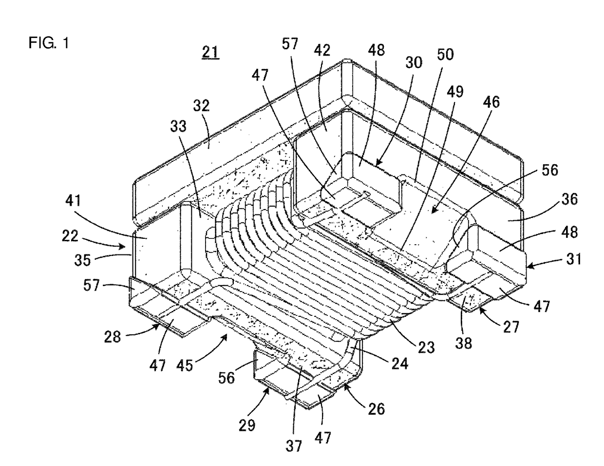
[0042]A wound coil 21 according to a first embodiment of the present disclosure is described with reference to FIG. 1 to FIG. 5. The wound coil 21 forms a common mode choke coil.
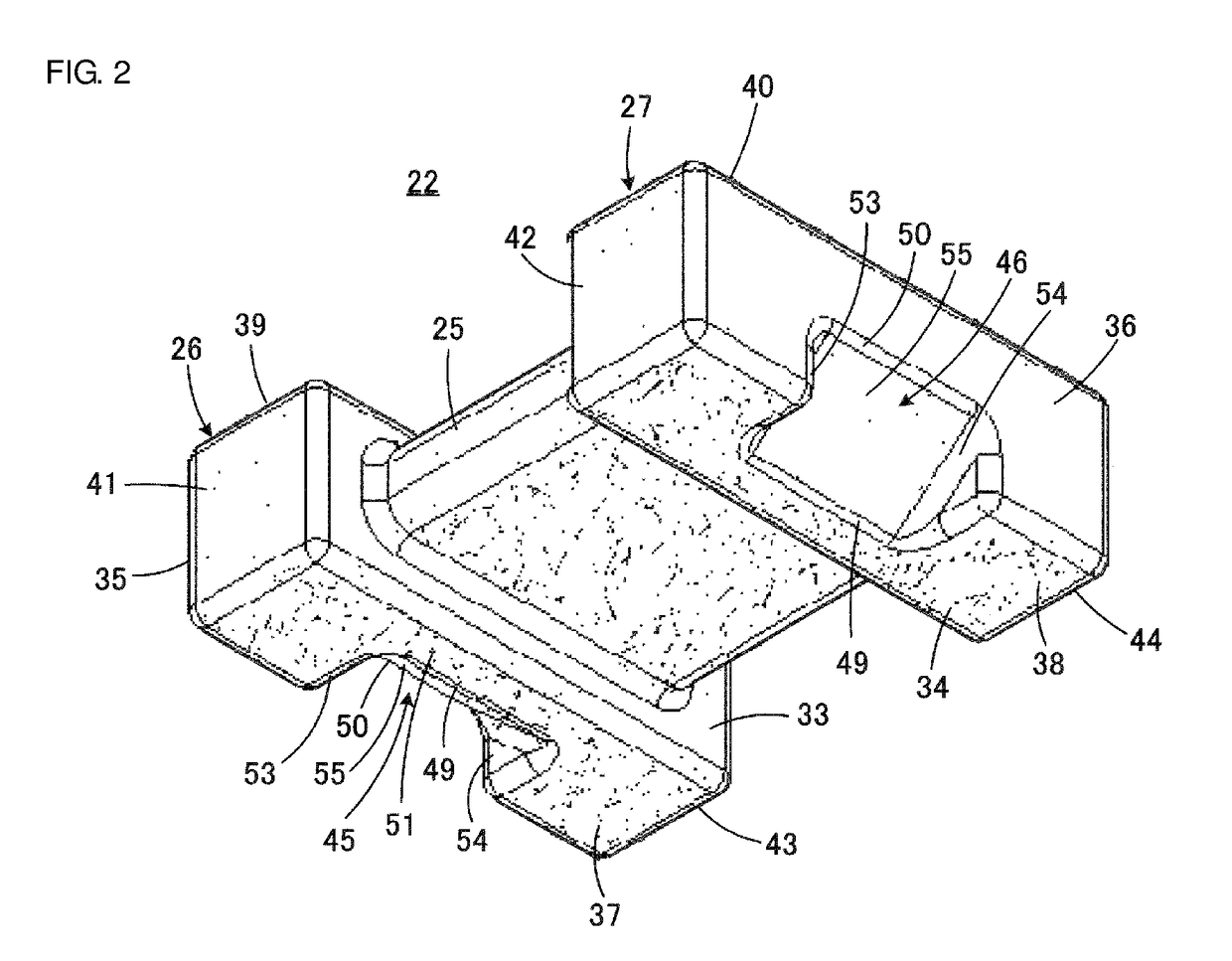
[0043]As illustrated in FIG. 1, the wound coil 21 includes a drum core 22, and a first wire 23 and a second wire 24, each of which forms an inductor. The drum core 22 is made of an electrically insulating material, more specifically, a material such as alumina, an example of a dielectric, Ni—Zn ferrite, an example of a magnetic substance, or a resin. As illustrated in FIG. 2 in detail, the drum core 22 has a rounded quadrangular section as a whole. The wires 23 and 24 are made of, for example, insulation coated copper wires.
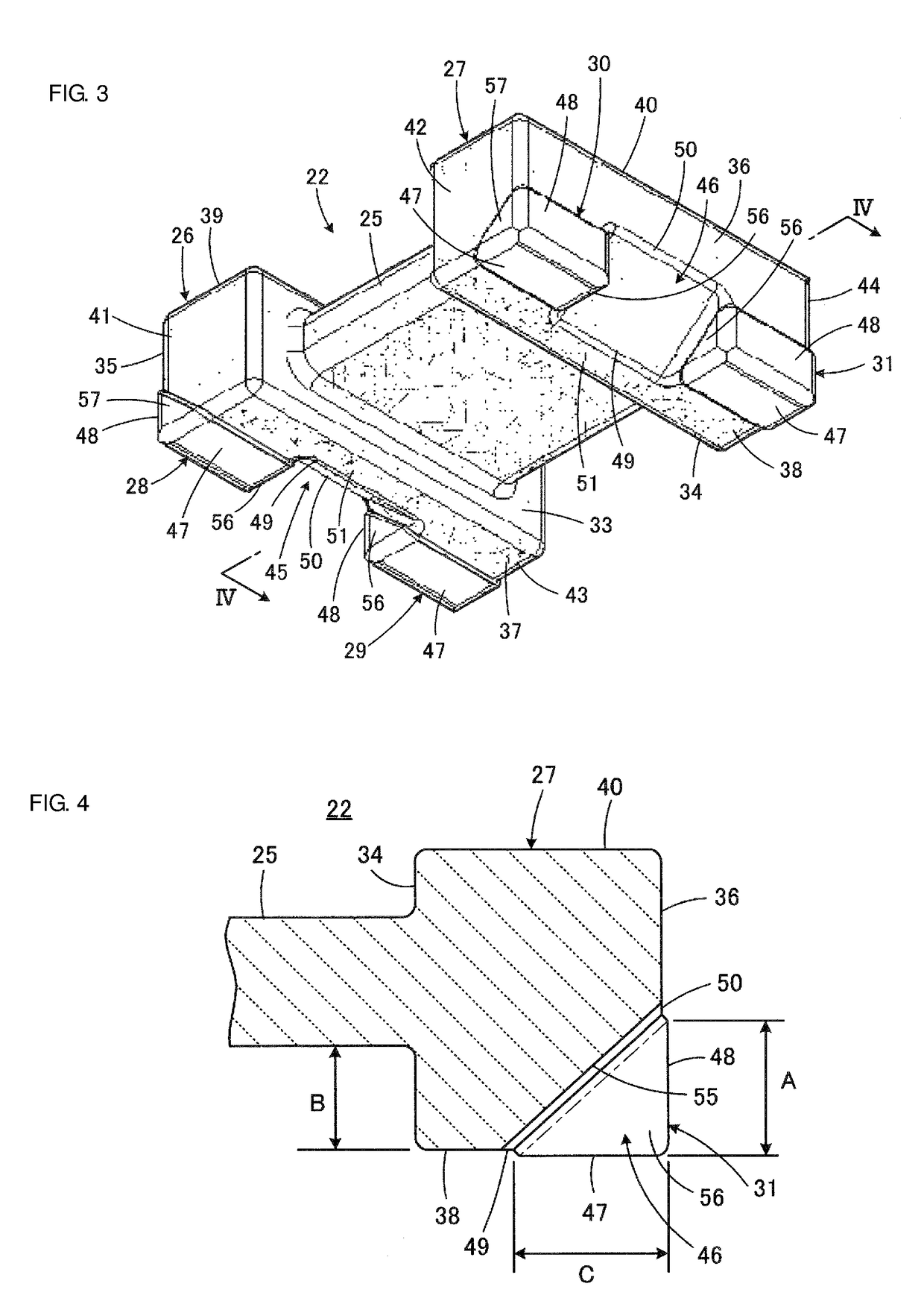
[0044]As illustrated in FIG. 2 in detail, the drum core 22 includes a wound core 25, and a first flange 26 and a second flange 27, disposed at end portions of the wound core 25. The first and second wires 23 and 24 are helically wound around the wound core 25 substantially the same number...
PUM
| Property | Measurement | Unit |
|---|---|---|
| thickness | aaaaa | aaaaa |
| thickness | aaaaa | aaaaa |
| angle of inclination | aaaaa | aaaaa |
Abstract
Description
Claims
Application Information