
Methods and systems for operating a mobility service vehicle

a technology for mobility services and lifting mechanisms, applied in the direction of loading/unloading vehicle arrangment, vehicle maintenance, transportation items, etc., can solve the problems of reducing the practicality of lifting mechanisms, affecting the operation of lifting mechanisms, so as to reduce the possibility of vehicle movement during lifting mechanism operation, reduce the effect of rolling the vehicle, and reduce the effect of lifting mechanism

Active Publication Date: 2018-12-06
FORD GLOBAL TECH LLC
View PDF0 Cites 10 Cited by
  • Summary
  • Abstract
  • Description
  • Claims
  • Application Information

AI Technical Summary

Benefits of technology

The patent text describes a method for a vehicle that allows for better coordination between the operation of a lifting mechanism and engine idle-stop and restart events. By shifting the transmission gear position to park and engaging the electronic park brake before operating the lifting mechanism, the possibility of vehicle movement during operation or rolling on a slope may be reduced. By restarting the engine and resending the original transmission position after operation of the lifting mechanism, the vehicle may operate seamlessly. This method helps to efficiently use engine power, reduce reliance on battery charge, and improve fuel economy in the vehicle.

Problems solved by technology

Also, the operation of the ramp may be inhibited if the vehicle door is not opened.
However, the inventors herein have recognized potential issues with such systems.
As one example, during an engine idle-stop, when the engine combustion is disabled, operation of the lifting mechanism may be requested and the state of charge (SOC) of a battery providing power to the lifting mechanism may not be sufficient for operating the lifting mechanism, thereby delaying operation of the lifting mechanism.
Also, in the system of Song et al., during an engine idle-stop even if the vehicle is at rest, the lifting mechanism may not be operated if the vehicle is not at park (such as when the transmission position is not park).
When the vehicle is parked on a slope, even with the transmission at park, the vehicle may roll and may not be stable enough to operate the lifting mechanism.
If engine idle-stop conditions are met and a request for operation of the lifting mechanism is received, the engine may shut down without providing the power needed for operating the lifting mechanism, thereby delaying operation of the lifting mechanism.

Method used


Image

  • Methods and systems for operating a mobility service vehicle
  • Methods and systems for operating a mobility service vehicle
  • Methods and systems for operating a mobility service vehicle

Examples


Embodiment Construction

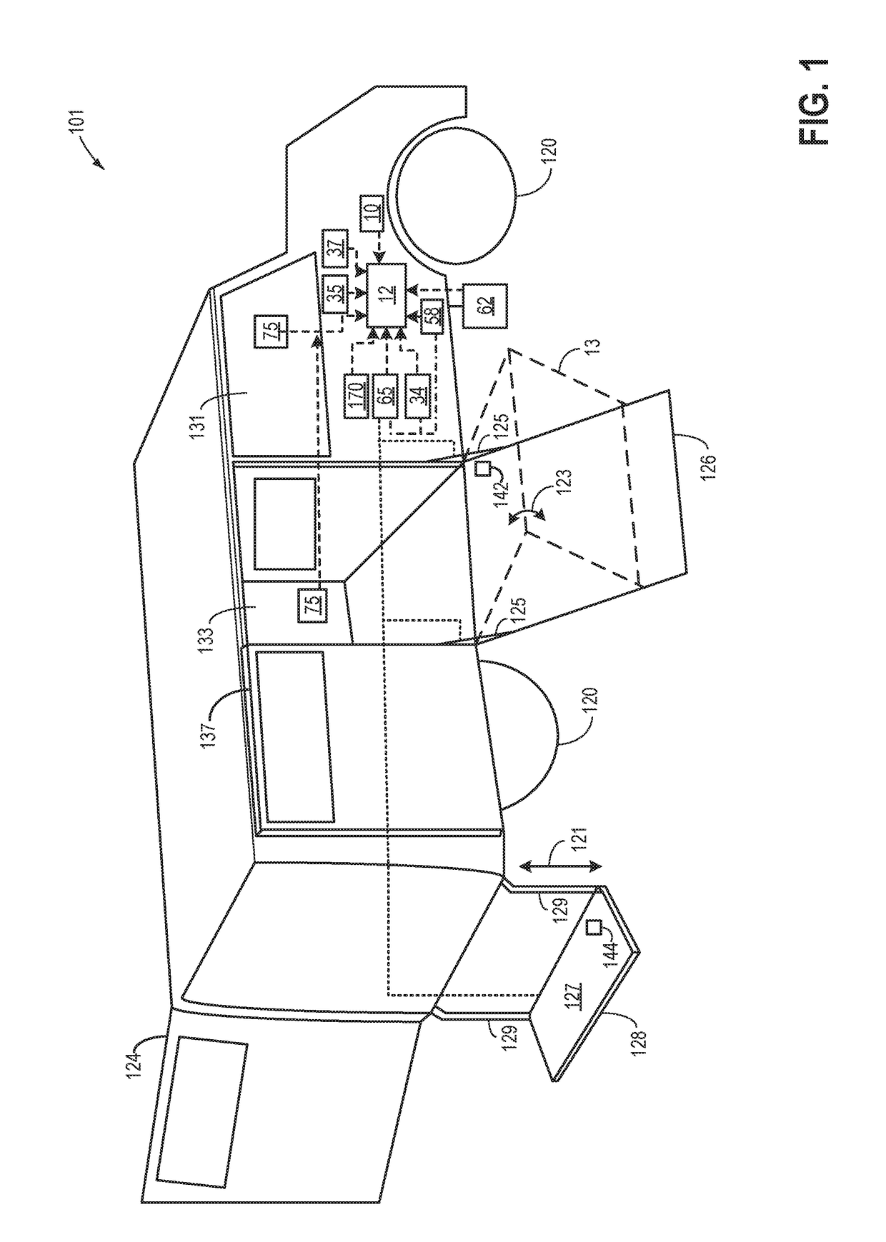
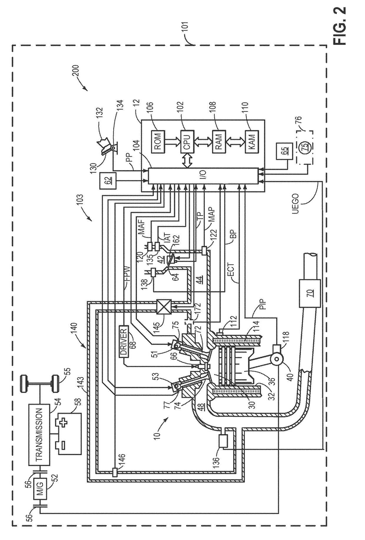
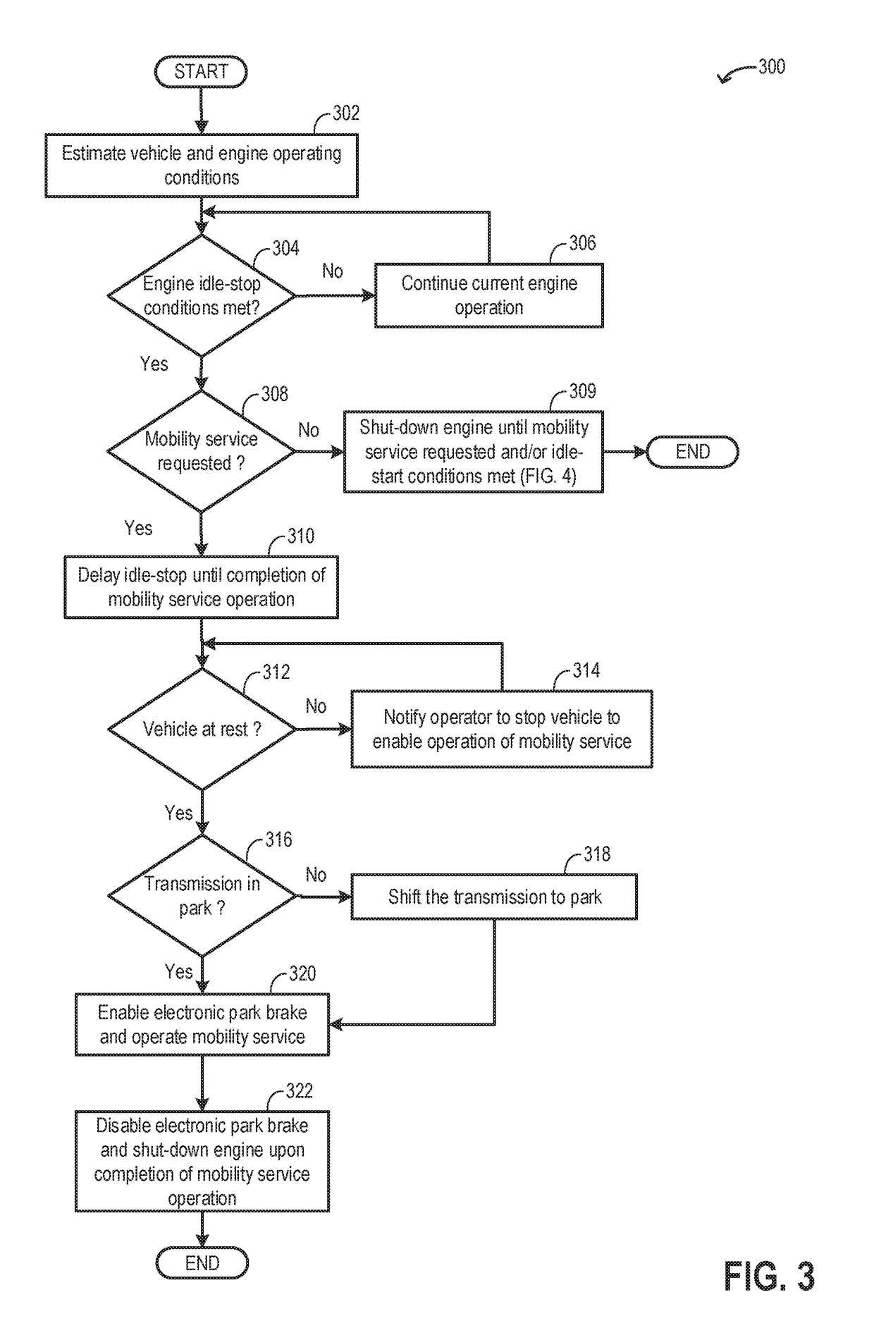
[0014]The following description relates to systems and methods for controlling operation of a vehicle fitted with a lifting mechanism. An example vehicle (herein referred to as a mobility vehicle) equipped with a lifting mechanism is shown in FIG. 1 and an example engine system of the mobility vehicle is shown in FIG. 2. An engine controller may be configured to perform control routines, such as example routines of FIGS. 3 and 4, to adjust operation of each of the engine system and the transmission system of a mobility vehicle to operate a lifting mechanism. An example operation of the engine system and the transmission system of a mobility vehicle during an engine idle-stop is shown in FIG. 5.

[0015]FIG. 1 shows an example mobility vehicle 101 fitted with a plurality of lifting mechanisms. The mobility vehicle 101 may be an on-road operated passenger vehicle equipped to transport passengers using mobility devices, such as a wheel chair, scooter, etc. The vehicle 101 may comprise whe...


PUM


Abstract

Methods and systems are provided for operation of a lifting mechanism coupled to a mobility service vehicle. In one example, a method may include, during an engine idle-stop, in response to a request for operation of a lifting mechanism used by mobility devices to access the vehicle, the transmission may be shifted to park, an electronic braking system may be enabled, and the engine may be restarted to provide power for operation of the lifting mechanism.

Description

FIELD[0001]The present description relates generally to methods and systems for controlling operation of a lifting mechanism coupled to a mobility service vehicle.BACKGROUND / SUMMARY[0002]Vehicles may be equipped with lifting mechanisms such as ramps and chairlifts for facilitating access of a physically impaired person using a mobility device such as a wheelchair. In response to a command by an operator, a ramp may be lowered from an open vehicle door to reach a pavement. Once the ramp has been used by the passenger to board the vehicle, the ramp may be folded and stowed under the floor of the vehicle cabin. Power from an on-board hydraulic system and / or an electric motor may be used for operating the lifting mechanism. Engine power may be used to charge an on-board battery supplying power to the hydraulic system and / or the electric motor.[0003]Various approaches are provided for operating a lifting mechanism in a vehicle. In one example, as shown in US20100332085, Song et al. teach...

Claims


Application Information

Patent Timeline
Patent Type & Authority Applications(United States)
IPC IPC(8): A61G3/06B60P1/44B60S9/14
CPCA61G3/062B60P1/445A61G3/067A61G3/061B60P1/431B60P1/4442B60P1/4471B66F9/07572
Inventor KHAFAGY, HAFIZ SHAFEEKSIDDIQUI, SIRAJAWADI, AHMEDBULAT, BENNORWOOD, JOSHUA
Owner FORD GLOBAL TECH LLC
Learn More