Long Persistent Luminescence Emitter and Long Persistent Luminescent Element

a luminescent element and luminescence emitter technology, applied in the direction of luminescent compositions, chemistry apparatus and processes, etc., can solve the problems of difficult to obtain a uniform long persistent luminescent film, high production cost, and production steps, and achieve excellent long persistent luminescence properties and low cost

Active Publication Date: 2018-12-06
OKINAWA INST OF SCI & TECH SCHOOL
View PDF1 Cites 6 Cited by
  • Summary
  • Abstract
  • Description
  • Claims
  • Application Information

AI Technical Summary

Benefits of technology

[0037]The long persistent luminescence emitter of the invention can exhibit persistent luminescence for a long time due to the functions of specific electron-accepting and electron-donating molecules without the use of any inorganic materials containing rare-earth elements. Thus, according to the long persistent luminescence emitter, a long persistent luminescent element which exhibits excellent long persistent luminescence properties can be provided at a low cost.

Problems solved by technology

The long persistent luminescent materials composed of inorganic salts, however, have the following problems: the production steps are complicated because formation of high-quality crystals and regulation of the particle diameter are required; the production costs are high because the materials are produced by complicated production steps using expensive rare-earth elements; and it is difficult to obtain a uniform long persistent luminescent film because the long persistent luminescent film is formed using a solution of dispersed fine inorganic particles (a heterogeneous system) as a paint.
Moreover, transparency is difficult to realize.
Many long persistent luminescent materials composed of inorganic salts have drawbacks because their excitation wavelengths are in the ultraviolet region, which limits the application of an excitation source with little ultraviolet light.
Accordingly, there is a limit on the extension of the emission duration time with the conventional organic long persistent luminescent materials, and the fact is that sufficient emission duration time cannot be obtained.

Method used


Image

  • Long Persistent Luminescence Emitter and Long Persistent Luminescent Element
  • Long Persistent Luminescence Emitter and Long Persistent Luminescent Element
  • Long Persistent Luminescence Emitter and Long Persistent Luminescent Element

Examples


example 1

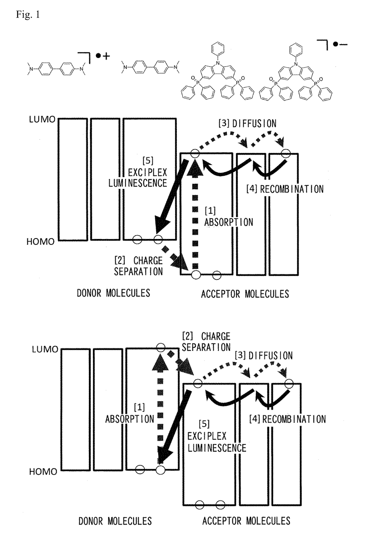
n and Evaluation of Long Persistent Luminescence Emitters Containing PO2CzPh as the Electron-Accepting Molecule and TMB as the Electron-Donating Molecule

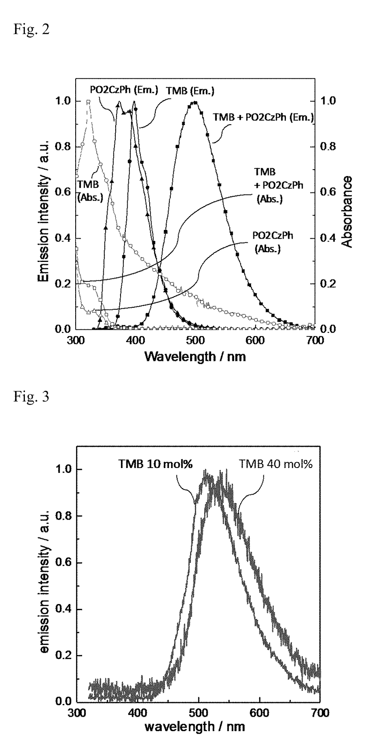
[0155]A quartz substrate was heated to a temperature of the melting point of PO2CzPh or higher (300° C. or higher) in a glovebox under a nitrogen atmosphere, and PO2CzPh was melted on the quartz substrate. TMB was added to and blended with the melted PO2CzPh at the concentration of 10 mol %, and the blend was cooled rapidly. A long persistent luminescent film in the glass state was thus formed and encapsulated using a glass substrate and an ultraviolet-cured resin. The ultraviolet absorption spectrum (Abs) of the produced long persistent luminescent film and its photoluminescence spectrum which was measured using excitation light of 340 nm at room temperature are shown in FIG. 2.

[0156]Separately from the film, a long persistent luminescent film of PO2CzPh and TMB was formed and encapsulated using a glass substrate and an ultraviolet...

experimental example 1

mpounds as Electron-Accepting Molecules

[0169]Long persistent luminescent films containing TMB at 10 mol % were formed and each encapsulated using a glass substrate and an ultraviolet-cured resin in the same manner as in Example 1 except that PO2CzH, DPEPO, PPT, 2CzPO, PyPO, P2CzPh, Estradiol, UGH3, mCP, mCBP or T2T was used instead of PO2CzPh and that the quartz substrate was heated to a temperature of the melting point of each compound or higher for melting the compound.

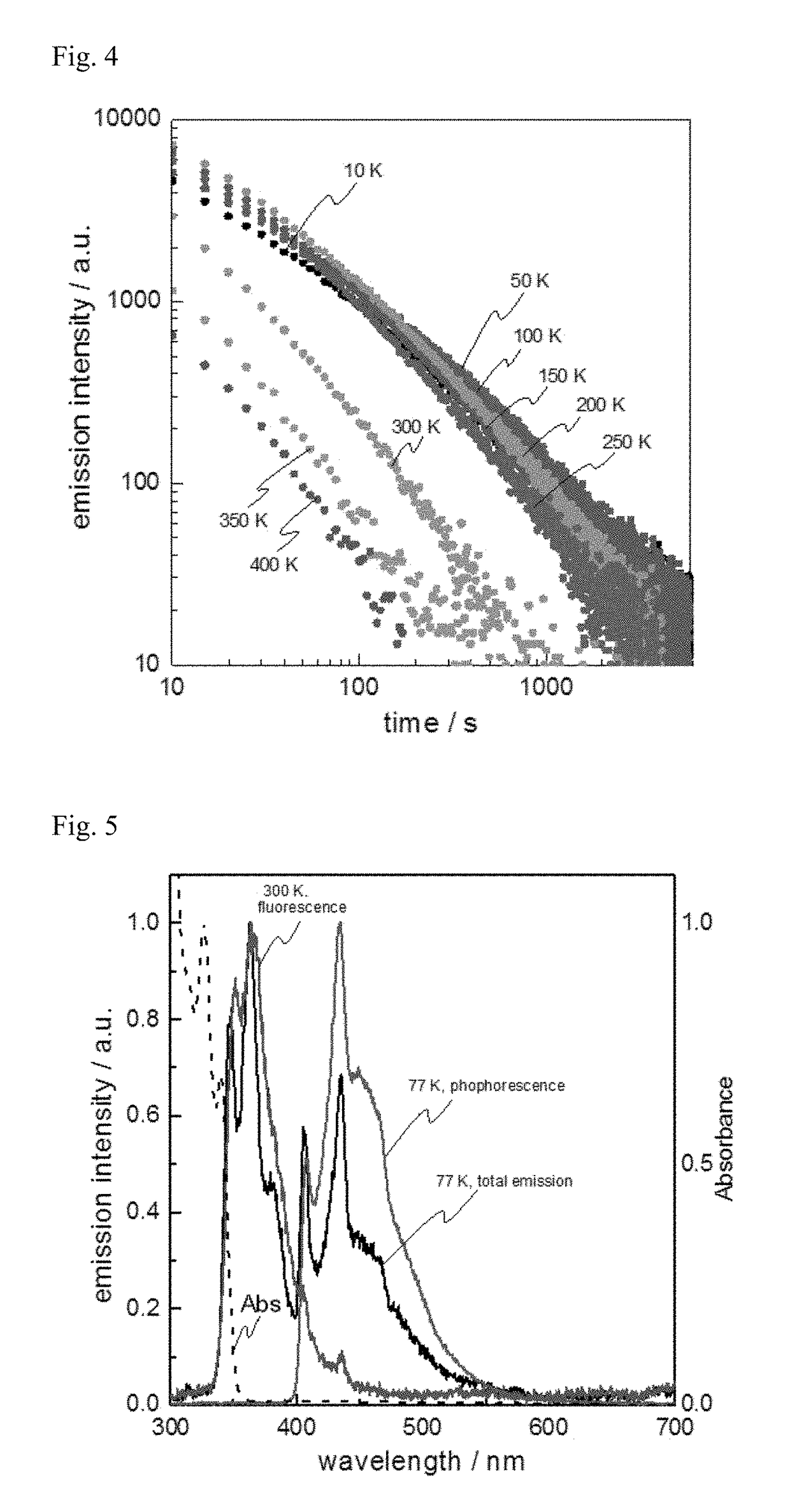
[0170]Excitation light of 340 nm was applied to the long persistent luminescent films containing PO2CzH, PPT, DPEPO or 2CzPO as the electron-accepting molecule, of the long persistent luminescent films produced in Experimental Example 1, and to the long persistent luminescent film produced in Example 1 at the temperature of 300 K for three minutes, and then the photo-irradiation was stopped. The changes in the emission intensity with time after that were measured. A log-log graph showing the changes in the emission ...

experimental example 2

mpounds as Electron-Donating Molecules

[0173]Long persistent luminescent films containing the electron-donating molecules at 10 mol % were formed and each encapsulated using a glass substrate and an ultraviolet-cured resin in the same manner as in Example 1 except that TPPD, TPA, PhCz, MeCz or mCP was used instead of TMB.

[0174]Excitation light of 340 nm was applied to the long persistent luminescent films produced in Experimental Example 2 at room temperature for three minutes, and then the photo-irradiation was stopped. The photographs of the long persistent luminescent films taken during the photo-irradiation and five seconds, five minutes and 20 minutes after the photo-irradiation stopped are shown in FIG. 10. The photographs in FIG. 10 are the photographs of the long persistent luminescent films containing the respective compounds indicated under the photographs as the electron-donating molecules, and for example, the photographs indicated by “TPPD” are the photographs of the lon...


PUM

PropertyMeasurementUnit
temperaturesaaaaaaaaaa
persistent luminescence duration timeaaaaaaaaaa

Abstract

The invention discloses a long persistent luminescence emitter which has an electron-donating molecule that is stable in the radical cation state and an electron-accepting molecule that is stable in the radical anion state and from which luminescence is observed at 10 K after photo-irradiation of the long persistent luminescence emitter stops. According to the disclosed invention, persistent luminescence can be exhibited for a long time with only organic compounds without the use of any rare-earth elements.

Description

TECHNICAL FIELD[0001]The present invention relates to a long persistent luminescence emitter which exhibits long-lived luminescence and to a long persistent luminescent element.BACKGROUND ART[0002]Long persistent luminescent materials are luminescent materials which store energy during the application of excitation light and emit light using the stored energy even after the application of the excitation light stops. Long persistent luminescent materials are used as luminescent paints for watch and clock dials which glow in the dark or at night, letters and diagrams of signs and guideboards and the like, and these materials have been recently applied to lights which can produce light with stored light energy without electricity supply.[0003]Of these long persistent luminescent materials, inorganic salts containing rare-earth elements such as Eu, Ce and Tb are especially known as long persistent luminescent materials which exhibit long-lived luminescence (for example, see PTL 1).CITAT...

Claims


Application Information

Patent Timeline
Patent Type & Authority Applications(United States)
IPC IPC(8): C09K11/06
CPCC09K11/06C09K2211/1007C09K2211/1014C09K2211/1018H10K50/00
Inventor KABE, RYOTAADACHI, CHIHAYA
Owner OKINAWA INST OF SCI & TECH SCHOOL
Why Eureka
Try Eureka