Thermal conduction structrure and manufacturing method thereof

a technology of conduction structure and manufacturing method, which is applied in the direction of semiconductor devices, semiconductor/solid-state device details, electrical devices, etc., can solve the problems of very limited thermal conduction and dissipation effects, large amount of conduct heat, chaotic flow of gaseous working fluid, etc., to improve the reflow speed of working fluid, improve the effect of reflow speed and deformation

Active Publication Date: 2018-12-06
TAIWAN MICROLOOPS CORP
View PDF4 Cites 10 Cited by
  • Summary
  • Abstract
  • Description
  • Claims
  • Application Information

AI Technical Summary

Benefits of technology

[0009]This disclosure has the following effects. The first capillary tissue and the second capillary tissue are contacted to improve the reflow speed of the working fluid. The penetrating hole has the dividing lines, so that the edge of the penetrating hole may be bent and deformed easily to produce the bending deformation which is favorable for passing through the exposed section and achieve a larger attaching and contacting area.

Problems solved by technology

Although the heat pipes contain a gaseous working fluid with consistent flowing direction, yet the amount of the conduct heat is very small due to the limitation of the volume of the heat pipes.
On the other hand, although the vapor chambers have a spacious heated area provided to be attached to a heat source for heat conduction, yet the flow of the gaseous working fluid is chaotic and the thermal conduction and dissipation effects are very limited.
Although the conventional thermal conduction structure has the thermal conduction and dissipation effects, it still has the following drawbacks.
Since the manufacturing process is very complicated, the complicated process is unfavorable for mass production.
In addition, the core rod is extended to the bottom end (which is a closed end) of the heat pipe, and thus it is difficult to remove the core rod from the heat pipe after the sintering process is finished.
In addition, the core rod is attached to a capillary tissue with a large area, so that the capillary tissue may be damaged or cracked during the process of removing the core rod, and the yield rate of the product will be poor.

Method used


Image

  • Thermal conduction structrure and manufacturing method thereof
  • Thermal conduction structrure and manufacturing method thereof
  • Thermal conduction structrure and manufacturing method thereof

Examples


Embodiment Construction

[0014]The technical contents of the present invention will become apparent with the detailed description of preferred embodiments accompanied with the illustration of related drawings as follows. It is noteworthy that the preferred embodiments are provided for illustrating this disclosure rather than restricting the scope of the disclosure.

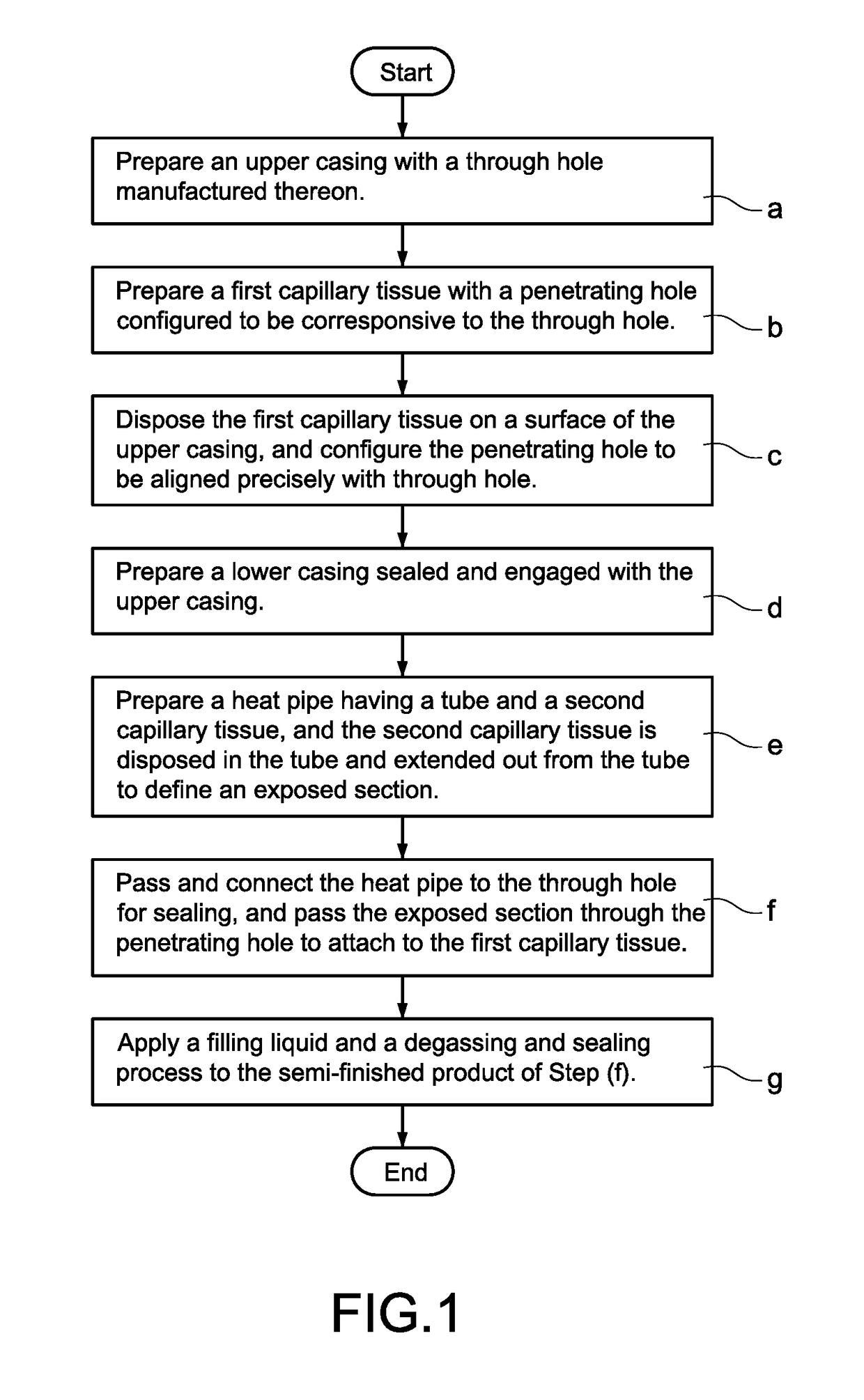
[0015]With reference to FIGS. 1 to 4 for a thermal conduction structure manufacturing method of this disclosure, the method comprises the following steps:

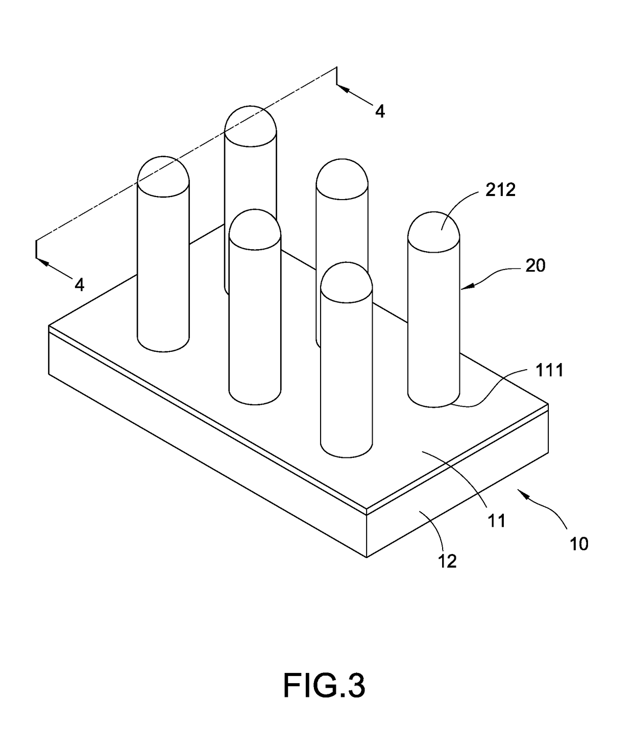
[0016](a) Prepare an upper casing 11, and manufacture the upper casing 11 to form a through hole 111 thereon. With reference to FIG. 2, the upper casing 11 may be made of aluminum, copper or their alloy, and a forming mold (not shown in the figure) is used to stamp and manufacture the upper casing 11 to form a plurality of through holes 111 on the upper casing 11. The quantity of through holes 111 may be selected according to actual requirements. For example, one through hole 111 may be selected ...


PUM


Abstract

In a thermal conduction structure and its manufacturing method, the thermal conduction structure includes a vapor chamber, a heat pipe and a working fluid. The vapor chamber includes an upper casing, a lower casing, and a cavity formed between the lower and upper casings. The upper casing has a through hole communicated with the cavity and a first capillary tissue disposed on the internal surface of the upper casing. The first capillary tissue has a penetrating hole corresponsive to the through hole. The heat pipe includes a tube and a second capillary tissue disposed in the tube and extended out from the tube to define an exposed section, and the heat pipe is passed and coupled to the through hole, and the exposed section is passed through the penetrating hole to attach to the first capillary tissue. The working fluid is filled in the cavity.

Description

FIELD OF THE INVENTION[0001]This disclosure relates to a thermal conduction technology, and more particularly to a thermal conduction structure and its manufacturing method.BACKGROUND OF THE INVENTION[0002]As the computing speed of electronic devices increases, more and more heat will be generated by the electronic device. To overcome the large amount of generated heat effectively, related manufacturers uses heat pipes and vapor chambers with good thermal conductivity extensively. Although the heat pipes contain a gaseous working fluid with consistent flowing direction, yet the amount of the conduct heat is very small due to the limitation of the volume of the heat pipes. On the other hand, although the vapor chambers have a spacious heated area provided to be attached to a heat source for heat conduction, yet the flow of the gaseous working fluid is chaotic and the thermal conduction and dissipation effects are very limited.[0003]To overcome the aforementioned problems, some manufa...

Claims


Application Information

Patent Timeline
Patent Type & Authority Applications(United States)
IPC IPC(8): H01L23/427H01L23/433
CPCH01L23/433H01L23/427H01L21/4882
Inventor LIN, CHUN-HUNG
Owner TAIWAN MICROLOOPS CORP
Why Eureka
Try Eureka