Relaxation oscillator and wireless device including relaxation oscillator

a relaxation oscillator and wireless device technology, applied in the direction of oscillator generator, pulse generation by logic circuit, pulse technique, etc., can solve the problems of large variation in oscillation frequency and may not be a stable frequency source for semiconductor chips, and achieve the effect of small temperature deviation in oscillation frequency

Active Publication Date: 2018-12-06
ABLIC INC
View PDF3 Cites 6 Cited by
  • Summary
  • Abstract
  • Description
  • Claims
  • Application Information

AI Technical Summary

Benefits of technology

[0019]According to the relaxation oscillator of the present invention, the relaxation oscillator having an extremely small temperature deviation in oscillation frequency can be provided.

Problems solved by technology

When the relaxation oscillator in related-art illustrated in FIG. 14 is formed on a semiconductor chip, there is a disadvantage in that the oscillation frequency largely varies due to a temperature coefficient of the variable resistor 105.
The relaxation oscillator in related-art formed on the semiconductor chip may not therefore be a stable frequency source.

Method used


Image

  • Relaxation oscillator and wireless device including relaxation oscillator
  • Relaxation oscillator and wireless device including relaxation oscillator
  • Relaxation oscillator and wireless device including relaxation oscillator

Examples


first embodiment

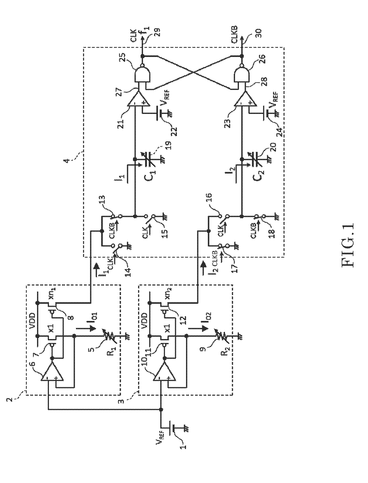
[0035]FIG. 1 is a diagram for illustrating a configuration of a relaxation oscillator according to a first embodiment of the present invention.

[0036]The relaxation oscillator according to the first embodiment has a reference voltage source 1, a current source circuit 2, a current source circuit 3, and an oscillation circuit 4.

[0037]The current source circuit 2 has a variable resistor 5, an operational amplifier 6, and PMOS transistors 7 and 8. The current source circuit 2 is supplied with a reference voltage VREF from the reference voltage source 1, and is supplied with a power supply voltage VDD from outside.

[0038]The current source circuit 3 has a variable resistor 9, an operational amplifier 10, and PMOS transistors 11 and 12. The current source circuit 3 is supplied with a reference voltage VREF from the reference voltage source 1, and is supplied with a power supply voltage VDD from outside.

[0039]In this case, the variable resistor 5 and the variable resistor 9 have first-order...

second embodiment

[0086]FIG. 5 is an illustration of a configuration of a relaxation oscillator according to a second embodiment of the present invention. FIG. 5 is an illustration of a further specific configuration of the relaxation oscillator for the first embodiment of the present invention.

[0087]The variable capacitor 19 shown in the first embodiment is formed by connecting in parallel K units of a unit capacitor 31 and a switch 32 connected in series. The variable capacitor 20 in the first embodiment is formed by connecting in parallel K units of a unit capacitor 33 and a switch 34 connected in series.

[0088]The capacitance of the variable capacitor 19 is controlled by a digital value SP1 from a variable capacitor setting terminal 35, and the capacitance of the variable capacitor 20 is controlled by a digital value SP2 from a variable capacitor setting terminal 36.

[0089]SP1 is a signal for controlling the number of switches 32 to be turned on, and SP2 is a signal for controlling the number of sw...

third embodiment

[0096]FIG. 6 is an illustration of a relaxation oscillator according to a third embodiment of the present invention. In the third embodiment, inverter circuits 39 and 40 having the same threshold voltage Vth (turnover voltage) are used instead of the comparators 21 and 23 in the second embodiment (FIG. 5), and an inverter circuit 37, which is the same as the inverter circuits 39 and 40, is used as the reference voltage source 1 in the second embodiment.

[0097]In the inverter circuit 37, an output voltage is fed back to the input by a feedback resistor 38, and hence the output voltage VREF converges to a threshold voltage Vth of the inverter. In the relaxation oscillator according to the third embodiment, the threshold voltage Vth of the inverter circuits 39 and 40 and VREF are always maintained in the same condition even when the power supply voltage VDD changes. The oscillation frequency is therefore independent of the power supply voltage VDD and the threshold voltage Vth of the in...


PUM


Abstract

Provided is a relaxation oscillator having an extremely small temperature deviation in oscillation frequency. A first current (I1) generated by a reference voltage source and a first resistor having a positive first-order temperature coefficient is supplied to a first variable capacitor (C1) for oscillation, and a second current (I2) generated by a reference voltage source and a second resistor having a negative first-order temperature coefficient is supplied to a second variable capacitor (C2) for oscillation. A product of a value of a ratio of a first current to a second current and a value of a ratio of a first-order temperature coefficient of the second resistor to a first-order temperature coefficient of the first resistor, and a value of a ratio of a capacitance of the first variable capacitor to a capacitance of the second variable capacitor have the same absolute value and opposite signs.

Description

RELATED APPLICATIONS[0001]This application claims priority under 35 U.S.C. § 119 to Japanese Patent Application No. 2017-108324 filed on May 31, 2017, the entire content of which is hereby incorporated by reference.BACKGROUND OF THE INVENTION1. Field of the Invention[0002]The present invention relates to a relaxation oscillator.2. Description of the Related Art[0003]FIG. 14 is an illustration of a circuit configuration of a relaxation oscillator in related-art. The relaxation oscillator has a reference voltage source 101, a current source circuit 102, and an oscillation circuit 104.[0004]The current source circuit 102 has a variable resistor 105, an operational amplifier 106, and PMOS transistors 107 and 108. The current source circuit 102 is supplied with a reference voltage VREF from the reference voltage source 101, and is supplied with a power supply voltage VDD from outside.[0005]In the current source circuit 102, a negative feedback loop is formed so that a voltage applied to ...

Claims


Application Information

Patent Timeline
Patent Type & Authority Applications(United States)
IPC IPC(8): H03K3/0231H03K3/011H03K4/08H03K3/013
CPCH03K3/02315H03K3/011H03K4/08H03K3/013H03B5/04H03B5/24H03K3/0231H03K4/502H03K3/03H03K4/501
Inventor TANAKA, TOSHIYUKISHEN, BIAOYONETANI, HIROYUKI
Owner ABLIC INC
Why Eureka
Try Eureka