Methods and devices for encoding and decoding a color picture

Inactive Publication Date: 2018-12-06
INTERDIGITAL MADISON PATENT HLDG SAS
View PDF1 Cites 13 Cited by
  • Summary
  • Abstract
  • Description
  • Claims
  • Application Information

AI Technical Summary

Benefits of technology

[0057]Thus, without increasing the bandwidth, and while maintaining a low complexity video encoding system, such an encoding method provides, during the decoding, different types of color pictures starting from a single HDR color picture.
[0058]It has to be noticed tha

Problems solved by technology

This limited non-linear representation does not allow correct rendering of small signal variations, in particular in dark and bright luminance ranges.
A trivial solution is simulcasting both these HDR and SDR color-graded pictures (or videos) on distribution infrastructure but the drawback is to virtually double the needed bandwidth compared to a legacy infrastructure adapted to broadcast a SDR picture (or video) such as HEVC main 10 profile (“High Efficiency Video Coding”, SERIES H: AUDIOVISUAL AND MULTIMEDIA SYSTEMS, Recommendation ITU-T H.265, Telecommunication Standardization Sector of ITU, October 2014).
The drawback of this solution is the lack of full backward compatibility because the obtained reduced-dynamic version of the picture (video) does not preserve the color grade of the SDR picture as wished by the Colorist.
It has to be noted th

Method used


Image

  • Methods and devices for encoding and decoding a color picture
  • Methods and devices for encoding and decoding a color picture
  • Methods and devices for encoding and decoding a color picture

Examples


first embodiment

[0209] FIG. 8a shows schematically a diagram of the steps of a method of decoding a HDR color picture IHDR_d and at least one first SDR color picture I1st_SDR_d, from a second SDR color picture of a received bitstream BR in accordance with an embodiment of the disclosure.

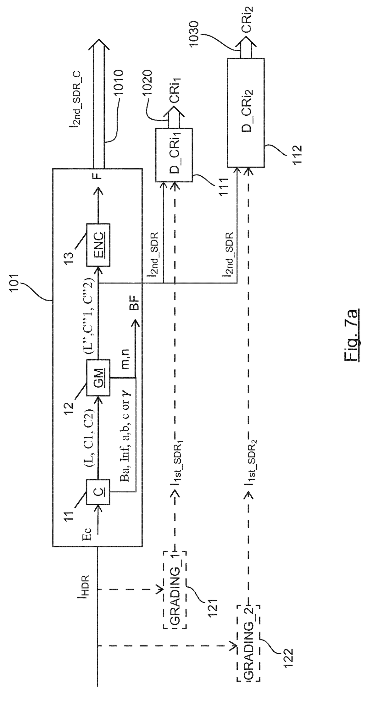
[0210]In particular, said bitstream BR is obtained, using the encoding method as previously described in relation with FIG. 2-7, from a High Dynamic Range (HDR) color picture and at least one first Standard Dynamic Range (SDR) color picture, said bitstream BR comprising at least one encoded second Standard Dynamic Range (SDR) color picture I2nd_SDR_C and also at least one piece of color remapping information CRi associated with said at least one encoded second Standard Dynamic Range (SDR) color picture I2nd_SDR_C, said at least one piece of color remapping information being used to obtain an approximation of said at least one first Standard Dynamic Range (SDR) color picture from said encoded second Standard Dynamic ...

second embodiment

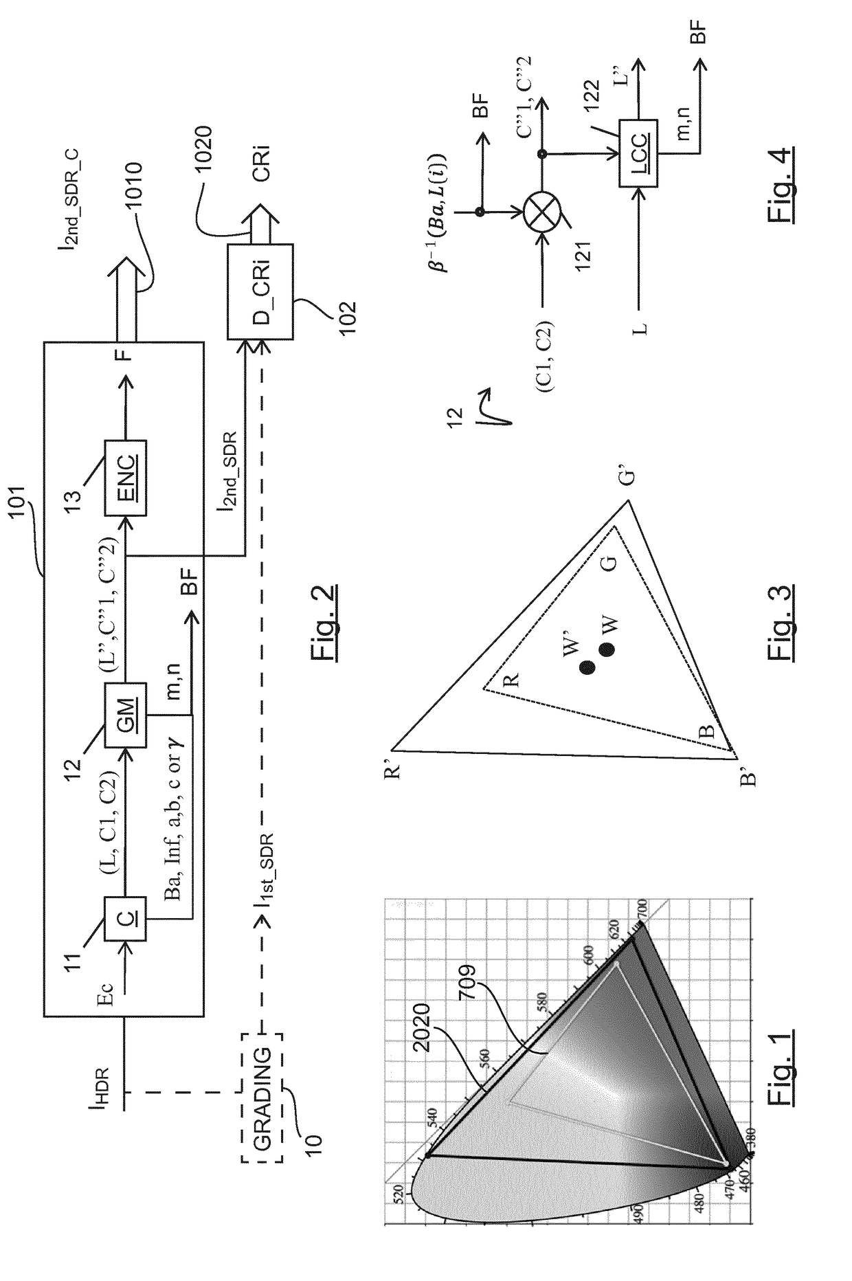
[0280]When the OETF fulfills the commutation conditions, according to the step 230, illustrated in FIG. 11b, in step 232, two intermediate components C′1 and C′2 are obtained by scaling the two chrominance components C1 and C2 by the factor OEFT(r(L(i))) where OETF is the function used in step 171 in FIG. 6:

C′1(i)=C1(i)OETF(r(L(i)))C′2(i)=C2(i)OETF(r(L(i)))

[0281]where r(L(i)) is the factor given by step 160 that depends on the value of a pixel i of the final luminance component L, C′1(i),C′2(i) is respectively the value of the pixel i of the component C′1 and C′2, C1 (i), C2 (i) is respectively the value of the pixel i of the component C1 and C2.

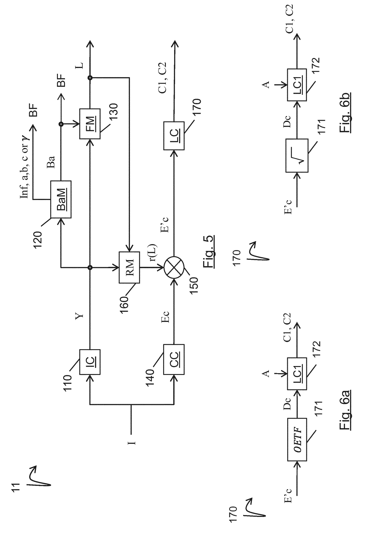
[0282]In step 231, a module ILEC obtains the three color components Ec from the first component Y and the two intermediate chrominance components C′1, C′2 as above explained.

[0283]According to a variant of this second embodiment, the OEFT is a square root function and the EOTF is then a square function. Then, in step 232 in FIG. 11b, the two...


PUM


Abstract

The present disclosure generally relates to a method and device of encoding a High Dynamic Range (HDR) color picture and at least one first Standard Dynamic Range (SDR) color picture, said method comprising encoding (101) a second Standard Dynamic Range (SDR) color picture obtained from the HDR color picture; According to the present disclosure, said method further comprises determining (102) at least one piece of color remapping information, from said second Standard Dynamic Range (SDR) color picture to said at least one first Standard Dynamic Range (SDR) color picture, said at least one piece of color remapping information being used to obtain an approximation of said at least one first Standard Dynamic Range (SDR) color picture from said second Standard Dynamic Range (SDR) color picture.

Description

1. FIELD OF THE INVENTION[0001]The present disclosure generally relates to picture / video encoding and decoding. Particularly, but not exclusively, the technical field of the present disclosure is related to encoding / decoding of both a color picture whose pixels values belong to a High Dynamic Range (HDR) and at least one color picture whose values belong to a Standard Dynamic Range (SDR) and who is obtained by a color-grading post-production operation applied on said High Dynamic Range (HDR) color picture.2. TECHNICAL BACKGROUND[0002]The present section is intended to introduce the reader to various aspects of art, which may be related to various aspects of the present disclosure that are described and / or claimed below. This discussion is believed to be helpful in providing the reader with background information to facilitate a better understanding of the various aspects of the present disclosure. Accordingly, it should be understood that these statements are to be read in this ligh...

Claims


Application Information

Patent Timeline
IPC IPC(8): H04N19/60H04N9/77G06T5/00G06T5/10
CPCH04N19/60H04N9/77G06T5/009G06T5/10H04N9/643H04N9/68H04N19/30H04N19/172H04N19/186
Inventor LELEANNEC, FABRICELASSERRE, SEBASTIENANDRIVON, PIERRE
Owner INTERDIGITAL MADISON PATENT HLDG SAS
Why Eureka
Try Eureka