
Tire Tread Comprising Incisions

Inactive Publication Date: 2018-12-13
MICHELIN & CO CIE GEN DES ESTAB MICHELIN
View PDF5 Cites 0 Cited by
  • Summary
  • Abstract
  • Description
  • Claims
  • Application Information

AI Technical Summary

Benefits of technology

The technical effect of this patent is to provide a tire tread that optimizes braking characteristics, reduces the braking distance on snow-covered ground, and improves braking distance on dry ground.

Problems solved by technology

The two arrangements described above are relatively complex and involve complicated manufacturing processes with expensive tooling.
However, the production of the lines of patterns requires a complex mould, with moulding / demoulding operations that are not very easy and expensive.

Method used


Image

  • Tire Tread Comprising Incisions
  • Tire Tread Comprising Incisions

Examples


Embodiment Construction

Definitions

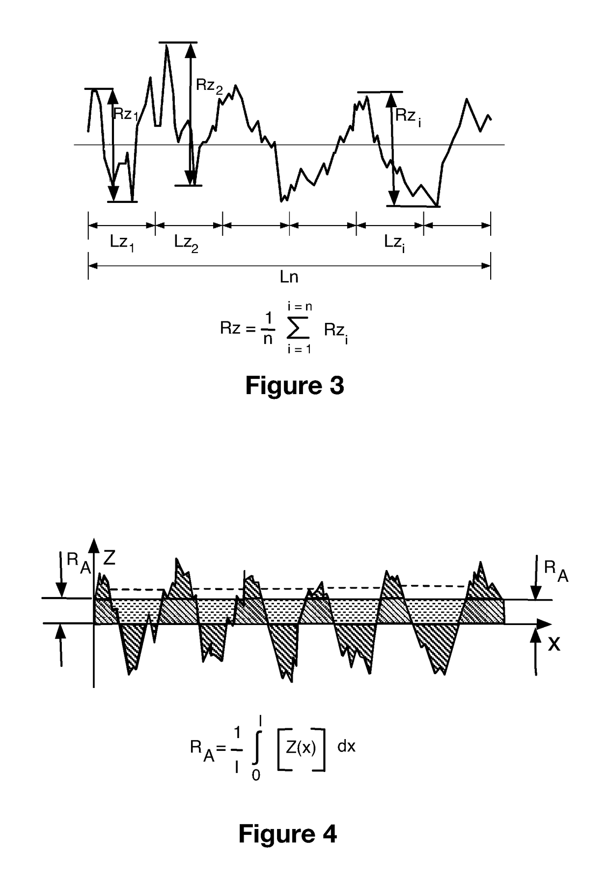
[0031]In order to calculate the roughness Rz of a surface, a given length of the surface to be evaluated, referred to as evaluation length Ln, is cut into n base lengths Lz of identical length, as is illustrated in FIG. 3. On each of these base lengths, an individual profile height Rzi, which is the sum of the greatest of the protruding heights and the greatest of the recessed depths of the profile of the surface within the base length Lzi, is determined. The mean height Rz is the arithmetic mean of the individual values Rzi over all of the base lengths considered (standard DIN 4768; 1990) and is expressed by the following formula:

Rz=1n∑i=1i=nRzi

[0032]In order to calculate the roughness RA of a surface, RA: is the arithmetic mean of all the ordinates of the profile within the base length, as is illustrated in FIG. 4, according to the following formula:

RA=1l∫0l[Z(x)]dx

[0033]A “tire” means all types of resilient tread, whether or not it is subjected to an internal pressure....


PUM


Abstract

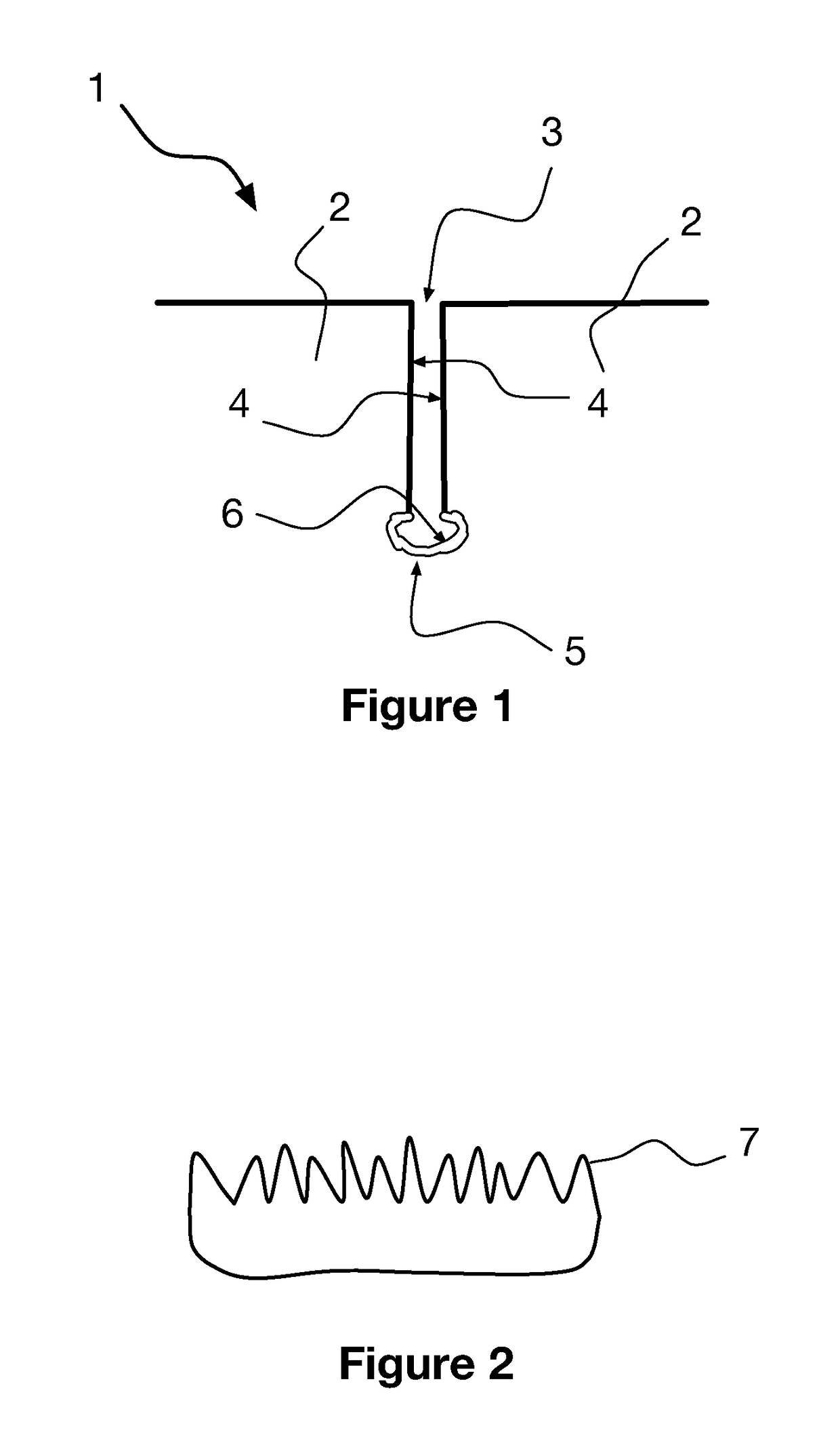
Tire tread (1) made of elastomeric material, having a tread surface intended to come into contact with a road surface when the tire rolls. The tread includes a plurality of cuts opening onto the tread surface, each cut having a sipe (3) delimited by facing first walls (4), and a widening zone (5) delimited by second walls (6) widening the sipe in the depth of the tread, the roughness of the first walls (4) being different from the roughness of the second walls (6) of material.

Description

TECHNICAL FIELD OF THE INVENTION[0001]The present invention relates to a motor vehicle tire tread. It relates more particularly to a tire tread provided with sipes.PRIOR ART[0002]The document EP1015261 describes a tread pattern for a tread and more particularly a tread pattern that changes as the tread wears down. Moreover, according to one particular embodiment, the document presents a block provided with a channel, the profile of which is 0-shaped or droplet-shaped. This channel communicates with a sipe, which extends as far as the tread. This sipe follows a route forming a succession of broken lines.[0003]The document EP0564435 presents a tire tread provided with profiling elements such as blocks, ribs extending in the peripheral direction, or similar configurations which are provided with thin siping cuts and / or grooves, the mutually opposite wall regions of which have a three-dimensional structure that differs at least in part on account of the presence of edges and surfaces re...

Claims


Application Information

Patent Timeline
IPC IPC(8): B60C11/12B60C11/03B60C11/00
CPCB60C11/1281B60C11/0323B60C11/0008
Inventor BLANCHET, ETIENNEPICHOIR, SEBASTIEN
Owner MICHELIN & CO CIE GEN DES ESTAB MICHELIN
Learn More