Wireless sending apparatus, wireless sending method, storage medium and baseband circuit
a wireless sending and wireless technology, applied in the field of wireless sending methods, wireless sending apparatuses, storage media and baseband circuits, can solve the problems of reducing the efficiency of using the frequency band, affecting the transmission of signals, and wasting frequency resources, so as to avoid performance, avoid performance, and optimize interference.
- Summary
- Abstract
- Description
- Claims
- Application Information
AI Technical Summary
Benefits of technology
Problems solved by technology
Method used
Image
Examples
first exemplary embodiment
[0057][First Exemplary Embodiment]
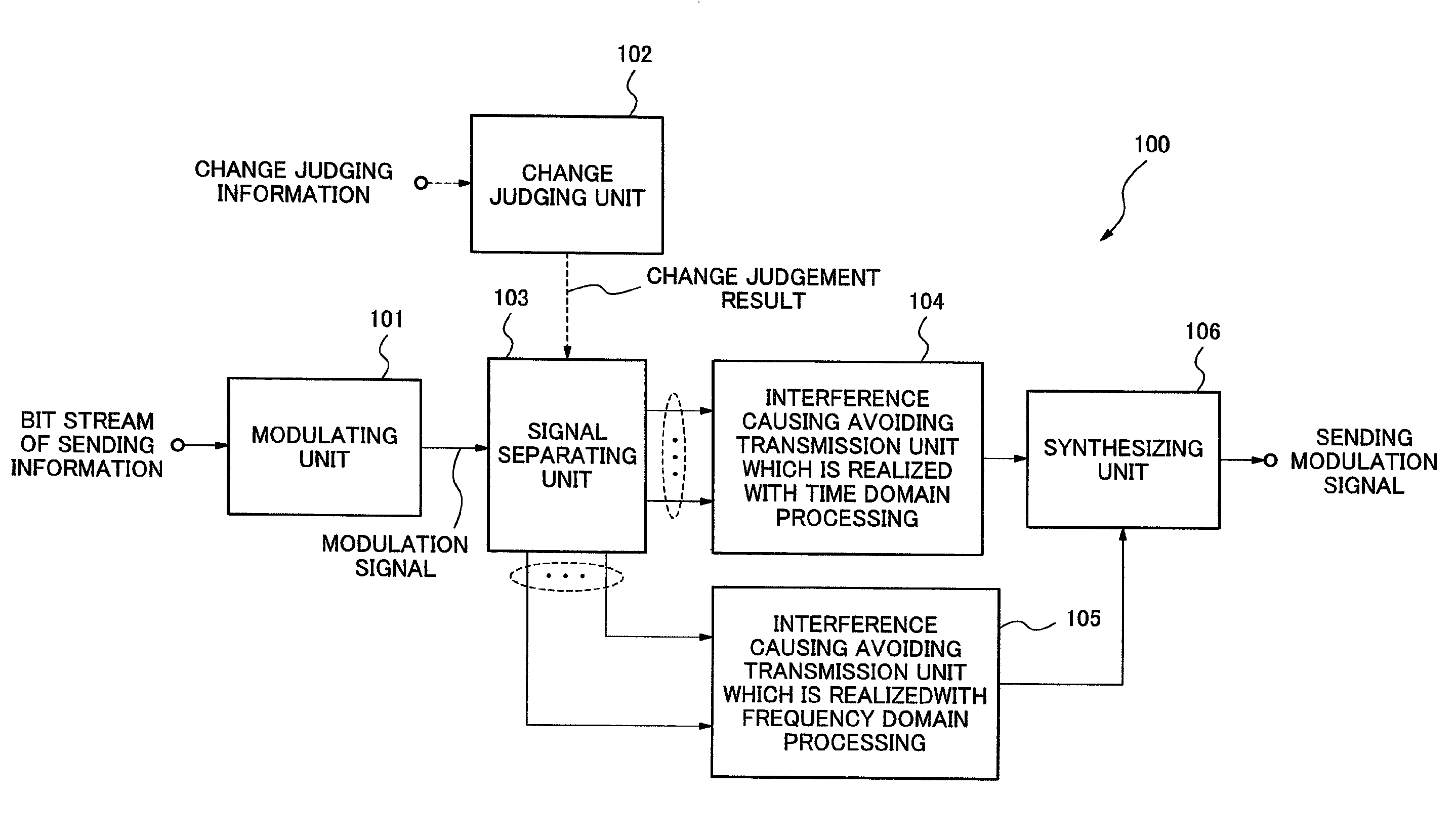
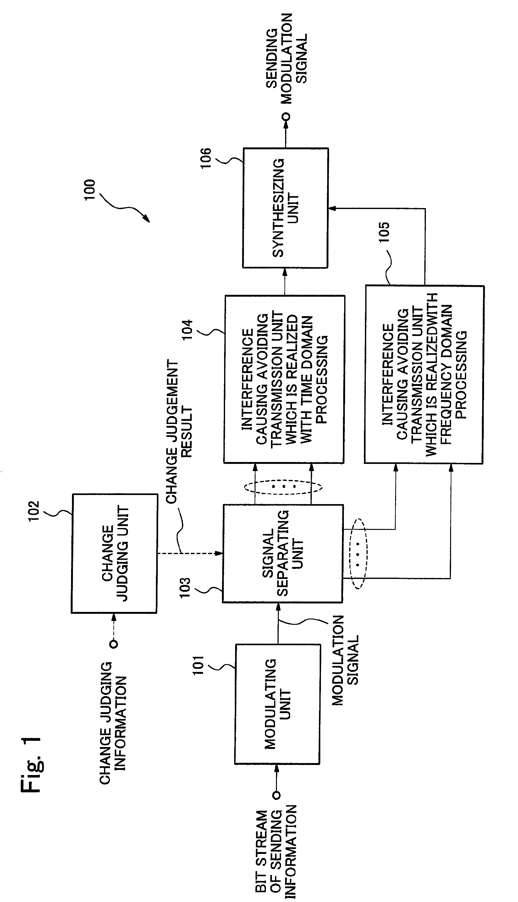
[0058]FIG. 1 is a block diagram showing an exemplary configuration of a baseband unit 100, which is included in a wireless sending apparatus according to a first exemplary embodiment of the present invention and which is processed by the digital processing. The baseband unit 100 includes a modulating unit 101, a change judging unit 102 (change judging means / change judging circuit) and a signal separating unit 103 (signal separating means / signal separating circuit). Furthermore, the baseband unit 100 includes an interference causing avoiding transmission unit 104 (first interference causing avoiding transmission means / first interference causing avoiding transmission circuit) which is processed in the time domain, an interference causing avoiding transmission unit 105 (second interference causing avoiding transmission means / second interference causing avoiding transmission circuit) which is processed in the frequency domain, and a synthesizing unit 10...
second exemplary embodiment
[0072][Second Exemplary Embodiment]
[0073]FIG. 5 is a block diagram showing an exemplary configuration of a baseband unit 500, which is included in a wireless sending apparatus according to a second exemplary embodiment of the present invention and which is processed by the digital processing. The baseband unit 500 includes an encoding unit 501, an interleaving unit 502, a modulating unit 503, a S / P (Serial / Parallel) conversion unit 504 (abbreviated as “S / P” in FIG. 5.), a sending power control unit 505, a multi-path delay measurement result acquiring unit 506, a transmission line loss estimating unit 507, a Window overlapping length control unit 508, a Time windowing / AIC changing judging unit 509 and a sensing unit 510. Furthermore, the baseband unit 500 includes a subcarrier mapping unit 511, IFFT units 512-1 and 512-2, P / S (Parallel / Serial) conversion units 513-1 and 513-2 (abbreviated as “P / S” in FIG. 5.), a CP adding unit 514-1, a GI (Guard Interval) adding unit 514-2, a Time wi...
third exemplary embodiment
[0160][Third Exemplary Embodiment]
[0161]FIG. 21 is a block diagram showing an exemplary configuration of a baseband unit 2000, which is included in a wireless sending apparatus according to a third exemplary embodiment of the present invention, and which is processed by the digital processing. A different point of the baseband unit 2000 from the baseband unit 500 according to the second exemplary embodiment shown in FIG. 5 is that the baseband unit 2000 uses the subcarrier weighting method instead of the AIC method as the interference causing avoiding transmission method which is processed in the frequency domain. Specifically, the baseband unit 2000 includes a Time windowing / subcarrier weighting changing judging unit 2109 instead of the Time windowing / AIC changing judging unit 509 shown in FIG. 5. Furthermore, the baseband unit 2000 includes a subcarrier weighting unit 2116 instead of the AIC symbol generating unit 516 shown in FIG. 5. According to the above-mentioned configuration...
PUM
 Abstract
Description
Claims
Application Information
 - R&D
- Intellectual Property
- Life Sciences
- Materials
- Tech Scout
- Unparalleled Data Quality
- Higher Quality Content
- 60% Fewer Hallucinations
Browse by: Latest US Patents, China's latest patents, Technical Efficacy Thesaurus, Application Domain, Technology Topic, Popular Technical Reports.
© 2025 PatSnap. All rights reserved.Legal|Privacy policy|Modern Slavery Act Transparency Statement|Sitemap|About US| Contact US: help@patsnap.com


