
Rotor

Active Publication Date: 2021-09-23
DELTA ELECTRONICS INC
View PDF0 Cites 0 Cited by
  • Summary
  • Abstract
  • Description
  • Claims
  • Application Information

AI Technical Summary

Benefits of technology

The present patent provides a rotor with enhanced structural strength, magnetic loop characteristic, and motor efficacy. The rotor has a first arc length radius that is greater than or equal to 0.2 times the minimum arc-cutting distance. This results in a decreased stress concentration factor and increased structural strength. Increasing the structural strength leads to improved motor performance. The entire motor characteristic is optimized for better performance.

Problems solved by technology

When the permanent magnet motor is operated at high speed, for example the rotating speed of the permanent magnet motor is 15000 rpm, centrifugal force generated by the rotor increases the stress concentration in the rotor so that the increased stress concentration weakens the structural strength of the rotor.
However, the magnetic loop characteristic of the permanent magnet motor is decreased while the structure of the rib is designed so that the efficacy of the motor is decreased.

Method used


Image

  • Rotor
  • Rotor
  • Rotor

Examples


Embodiment Construction

[0013]The present disclosure will now be described more specifically with reference to the following embodiments. It is to be noted that the following descriptions of preferred embodiments of this disclosure are presented herein for purpose of illustration and description only. It is not intended to be exhaustive or to be limited to the precise form disclosed.

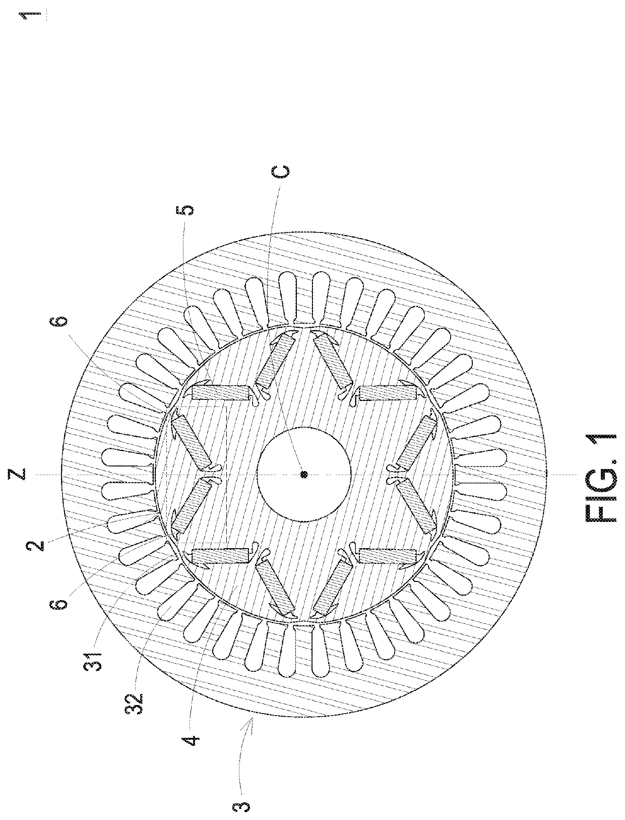
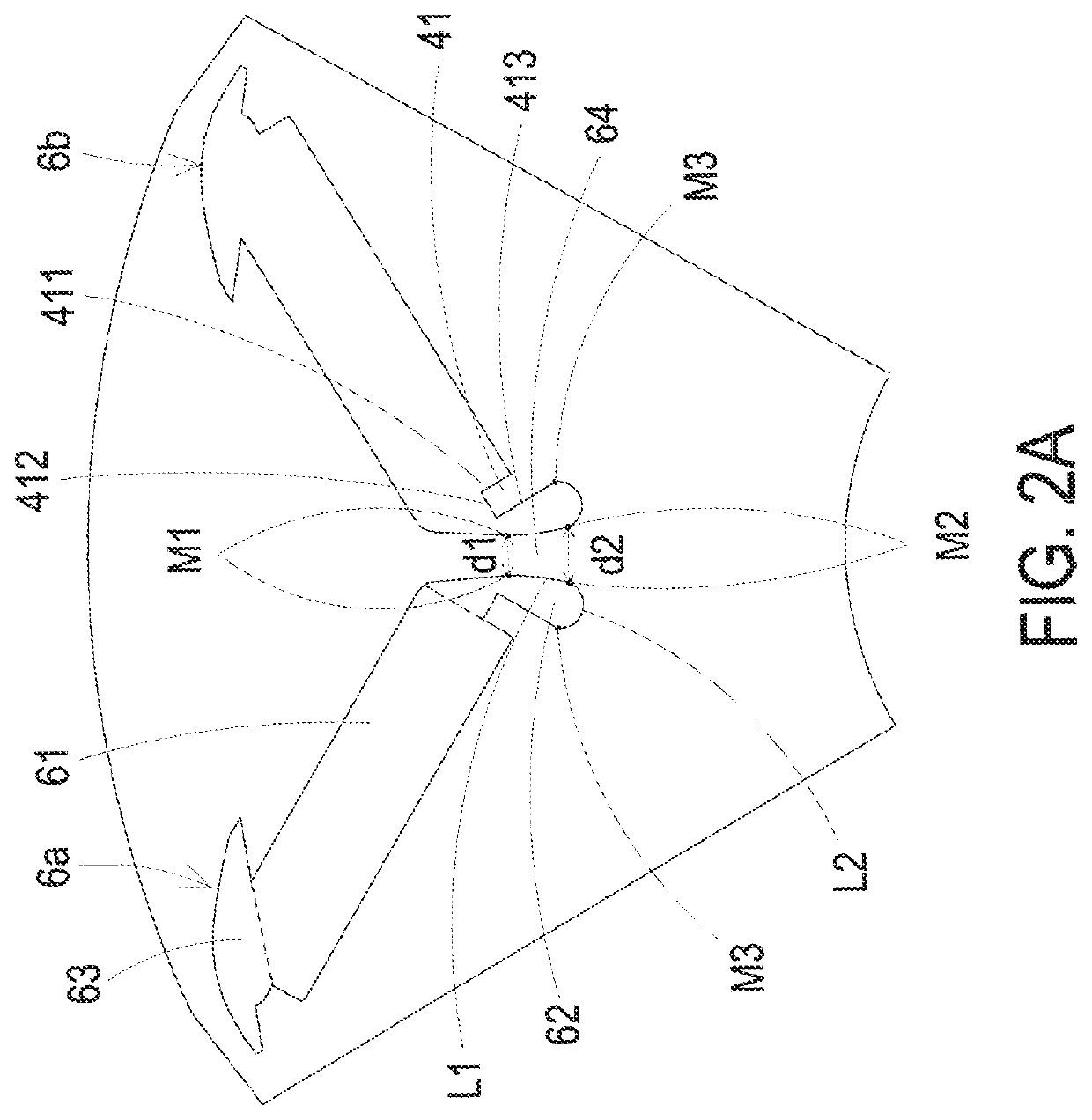
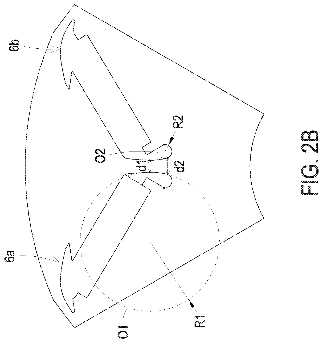
[0014]FIG. 1 is a schematic perspective view illustrating a rotor applied to a motor according to an embodiment of the present disclosure. FIGS. 2A and 2B are partial schematic perspective views illustrating the rotor of FIG. 1. As shown in FIGS. 1, 2A and 2B, a motor 1 is provided. The motor 1 includes a rotor 2 and a stator 3 matched with each other. Preferably but not exclusively, the combination of the rotor 2 and the stator 3 is implemented by means of an outer stator and an inner rotor. In this embodiment, the stator 3 includes a hollow portion 31, a plurality of gaps 32 and a plurality of windings (not shown in figures)....


PUM


Abstract

A rotor is provided. The rotor includes a main body, a plurality of magnets and a plurality of magnet-receiving slots. The plurality of magnet-receiving slots are disposed on the main body and disposed around a central axis. Each two adjacent magnet-receiving slots are symmetrical to each other. Each magnet-receiving slot includes a slot body and a first flux barrier connected with each other. Each magnet is contained in the corresponding slot body. Each first flux barriers includes a respective arc-cutting start point. A minimum arc-cutting distance is formed between the two respective arc-cutting start points. Each of the two respective arc-cutting start points is extended toward the central axis along an arc with a first arc length radius to define a first arc-cutting end point. The first arc length radius is greater than or equal to 0.2 times of the minimum arc-cutting distance.

Description

CROSS-REFERENCE TO RELATED APPLICATION[0001]This application claims priority to China Patent Application No. 202020336318.8 filed on Mar. 17, 2020. The entire contents of the above-mentioned patent application are incorporated herein by reference for all purposes.FIELD OF THE INVENTION[0002]The present disclosure relates to a rotor, and more particularly to a rotor with high structural strength.BACKGROUND OF THE INVENTION[0003]Generally, a permanent magnet electric machine or a permanent magnet motor includes a rotor and a stator. The stator includes a winding disposed thereon. The rotor includes a permanent magnet disposed thereon. The rotor is rotated by the magnetic force generated between the stator and the rotor.[0004]Mostly, a flower-petal-shaped rotor design is exploited in a conventional permanent magnet motor, which has a plurality of slots. The plurality of slots are disposed around the outer periphery of the rotor to organize the magnetic flux, so as to achieve the effect...

Claims


Application Information

Patent Timeline
IPC IPC(8): H02K1/27
CPCH02K1/276H02K2213/03H02K1/2766
Inventor LIU, YU-HSIANGYEH, TA-CHIENHSIAO, HSIANG-YUNYANG, CHIA-HSIANG
Owner DELTA ELECTRONICS INC
Learn More