Soft Switching Auxiliary Circuit, Three-Level Three-Phase Zero-Voltage Conversion Circuit

a conversion circuit and auxiliary circuit technology, applied in the field of power electronic technology, can solve the problems of multi-level technique, high-performance device to improve the switching frequency, extra switching loss, electromagnetic interference noise, etc., and achieve the effects of improving system switching frequency, reducing hard switching loss, and improving efficiency

Inactive Publication Date: 2018-01-18
EMERSON NETWORK POWER CO LTD
View PDF12 Cites 1 Cited by
  • Summary
  • Abstract
  • Description
  • Claims
  • Application Information

AI Technical Summary

Benefits of technology

[0022]The soft switching auxiliary circuit according to the present invention can reduce hard switching loss, improve system switching frequency, improve efficiency and reduce electromagnetic interference. By specific carriers, it can effectively reduce the number of times of auxiliary switch conversion, and can offset harmonics of specific order number, improve input harmonics characteristics, and reduce input current THDi; by the auxiliary coupling inductor in the soft switching circuit, it can mitigate the problem in regard to a too large auxiliary transistor stress resulting from sawtooth wave modulation, and automatically current-share the currents of the auxiliary branches, and optimize diode reverse recovery characteristic and current change waveforms; by an auxiliary active switching operation, it can force a coupling inductive voltage to be changed and converted to a current, and by using auxiliary inductor and capacitor resonance, it can cause energy feedback of the current through an auxiliary diode, and mitigate the problem of reverse recovery of the diode and the problem of hard switching of the main switch transistor.
[0023]There is no need for the zero-voltage conversion circuit according to the present invention to select one auxiliary circuit for each phase to solve the problem of hard switching of a main switch transistor. With the aid of diode single-phase conduction characteristic, by means of logic line AND, with use of one coupling inductor and one auxiliary switch transistor, one freewheeling diode and a plurality of anti-irrigation diodes, it solves the problem of hard switching of a main transistor in a circuit system, and reduces the cost of three-phase soft switching; meanwhile, by adopting specific sawtooth wave modulation, it simplifies PWM control such that the control characteristic of the system is more optimized and better.

Problems solved by technology

In the past, this goal was generally achieved by adopting a method of improving a switching frequency, but this will cause problems such as extra switching loss, electromagnetic interference noise, ringing and the like.
With the continuously-increasing requirements for high efficiency, high power density and low cost, use of a high performance device to improve the switching frequency and the multi-level technique still cannot satisfy the requirements in market competitions.
By increasing the switching frequency, application of the high performance device can reduce the inductance of a passive device and the volume of a transformer and a capacitor, but at the same time will result in an increase in switching loss, such that it is difficult to ensure the efficiency to be improved, thus failing to simultaneously satisfy the requirements of high power density and high efficiency.
In terms of the existing power electronic technique, there is still a long way to go for the application and promotion of the high performance devices, and the stability and cost of the application of the devices are constraint keys.
The proposal of topologies such as multi-level technique, interleaving, polymorphy and the like will improve the efficiency to some extent, but it still fails to satisfy market requirements.
Common power devices MOSFETs or IGBTs are developing rapidly, and also their performances are gradually improved and their loss are gradually lowered; however, hard switching is still a bottleneck for system high power density, high efficiency and low cost.

Method used


Image

  • Soft Switching Auxiliary Circuit, Three-Level Three-Phase Zero-Voltage Conversion Circuit
  • Soft Switching Auxiliary Circuit, Three-Level Three-Phase Zero-Voltage Conversion Circuit
  • Soft Switching Auxiliary Circuit, Three-Level Three-Phase Zero-Voltage Conversion Circuit

Examples


embodiment 1

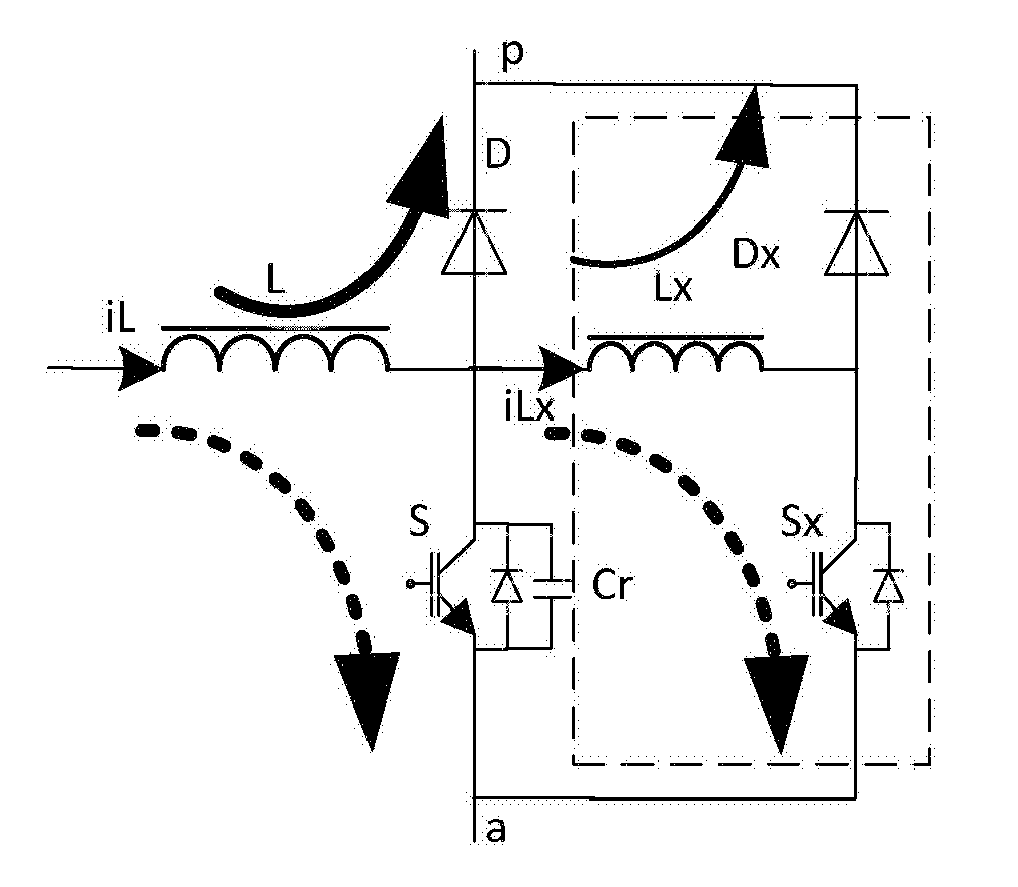
[0046]As shown in FIG. 1, Embodiment 1 of the present invention provides a soft switching auxiliary circuit, wherein the soft switching auxiliary circuit is connected in parallel with a main switch transistor of a main circuit, and comprises an auxiliary coupling inductor Lx, a clamping diode Dx and an auxiliary switch transistor Sx, wherein the auxiliary coupling inductor Lx has an input connected with a respective branch of the main circuit and an output connected with the clamping diode Dx, the clamping diode Dx is connected with one terminal of the main switch transistor S, another terminal of the the main switch transistor S is connected with the auxiliary switch transistor Sx, and the auxiliary switch transistor Sx is connected with the clamping diode Dx.

[0047]The soft switching auxiliary circuit (in the dashed frame) is directly connected in parallel with the main switch transistor S, which may achieve a soft switch-on effect of the auxiliary switch transistor Sx and the main...

embodiment 2

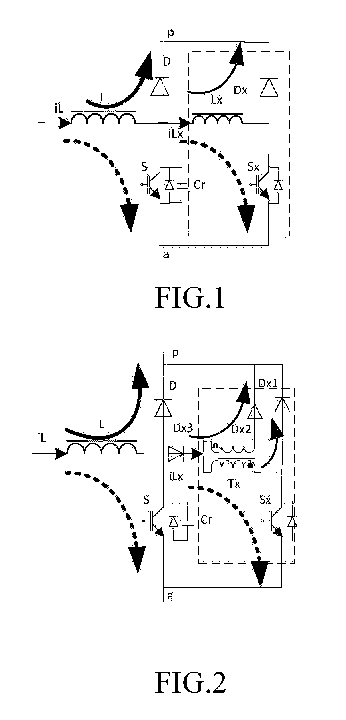
[0048]As shown in FIG. 2, Embodiment 2 of the present invention provides a soft switching auxiliary circuit, wherein the soft switching auxiliary circuit is connected in parallel with a main switch transistor of a main circuit, and comprises an auxiliary coupling inductor Tx, a clamping diode Dx1, an auxiliary switch transistor Sx, and a freewheeling diode Dx2, wherein the auxiliary coupling inductor Tx has an input connected with a respective branch of the main circuit and an output connected with the clamping diode Dx1, the clamping diode Dx1 is connected with one terminal of the main switch transistor S, another terminal of the main switch transistor S is connected with the auxiliary switch transistor Sx, the auxiliary switch transistor Sx is connected with the clamping diode Dx1, the auxiliary coupling inductor Tx has another output connected with the freewheeling diode Dx2, and the freewheeling diode is connected with one terminal of the main switch transistor S.

[0049]A unidire...

embodiment 3

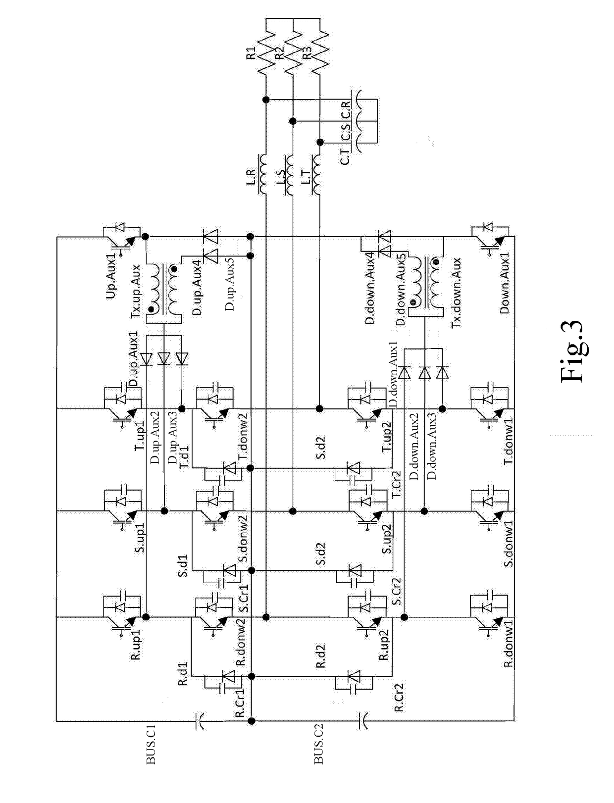
[0051]As shown in FIG. 3, Embodiment 3 of the present invention provides a three-level three-phase zero-voltage conversion circuit, comprising: a three-level three-phase main circuit and two auxiliary circuits, wherein upper arms of three branches of the three-level three-phase main circuit are respectively connected with one auxiliary circuit to constitute an upper soft switching circuit, and lower arms of the three branches of the three-level three-phase main circuit are respectively connected with the other auxiliary circuit to constitute a lower soft switching circuit, the two auxiliary circuits being connected with each other, wherein each of the two auxiliary circuits comprises an auxiliary coupling inductor, a clamping diode and an auxiliary switch transistor, wherein the auxiliary coupling inductor has an input connected with a respective branch of the main circuit and an output connected with the clamping diode, one terminal of the main switch transistor is connected with t...


PUM


Abstract

The present invention discloses a soft switching auxiliary circuit, comprising: an auxiliary coupling inductor configured to receive currents from a respective branch of a main circuit connected to the soft switching auxiliary circuit and perform a current sharing outputting; a clamping diode configured to receive an inductive voltage from the auxiliary coupling inductor and feed the inductive voltage back to a main switch transistor of the main circuit; an auxiliary switch transistor configured to receive a current from the main switch transistor of the main circuit and output the current to the clamping diode. The present invention further discloses a three-level three-phase zero-voltage conversion circuit. By means of the present invention, it is possible to reduce hard switching loss, to improve system switching frequency, to improve efficiency and to reduce electromagnetic interference.

Description

CROSS REFERENCE TO RELATED APPLICATION[0001]This application claims the priority of Chinese Patent Application No. 201610570714.5, entitled “SOFT SWITCHING AUXILIARY CIRCUIT, THREE-LEVEL THREE-PHASE ZERO-VOLTAGE CONVERSION CIRCUIT” filed with the Chinese Patent Office on Jul. 18, 2016, which is incorporated herein by reference in its entirety.TECHNICAL FIELD[0002]The present invention pertains to the filed of power electronic technology, and particularly to a soft switching auxiliary circuit and a three-level three-phase zero-voltage conversion circuit.BACKGROUND ART[0003]The development of power electronic devices is orientated at miniaturization, lightweight, high efficiency, and low cost. In the past, this goal was generally achieved by adopting a method of improving a switching frequency, but this will cause problems such as extra switching loss, electromagnetic interference noise, ringing and the like. Multi-level conversion technique enables the volume and weight of an output ...

Claims


Application Information

Patent Timeline
Patent Type & Authority Applications(United States)
IPC IPC(8): H02M3/158H02M3/335H02M1/42H03K17/16H02M7/217
CPCH02M3/1582H02M3/1588H02M3/33507H02M3/33592H02M1/4208H02M7/217H03K17/164H02M7/219H02M7/487Y02B70/10H02M1/342H02M1/0058
Inventor XU, FUBINHUANG, HAIBING, YANG
Owner EMERSON NETWORK POWER CO LTD
Why Eureka
Try Eureka