Water level measurement system and water level control system, and water level measurement method and water level control method using such systems

a technology of water level measurement and control system, which is applied in the direction of process and machine control, image enhancement, instruments, etc., can solve the problems of expensive and difficult to obtain miniaturized unmanned aerial vehicles (uavs) typified by unmanned helicopters for industrial us

Active Publication Date: 2018-12-13
PRODRONE CO LTD
View PDF3 Cites 11 Cited by
  • Summary
  • Abstract
  • Description
  • Claims
  • Application Information

AI Technical Summary

Benefits of technology

[0034]As described above, according to the water level measurement system pertaining to the present invention, it would become possible to measure a water level remotely without requiring a worker to go to the site. Also, accor

Problems solved by technology

Now, conventionally, miniature unmanned aerial vehicles (UAVs) which are typified by unmanned helicopters for indu

Method used


Image

  • Water level measurement system and water level control system, and water level measurement method and water level control method using such systems
  • Water level measurement system and water level control system, and water level measurement method and water level control method using such systems
  • Water level measurement system and water level control system, and water level measurement method and water level control method using such systems

Examples


first embodiment

[0043][Overall Configuration]

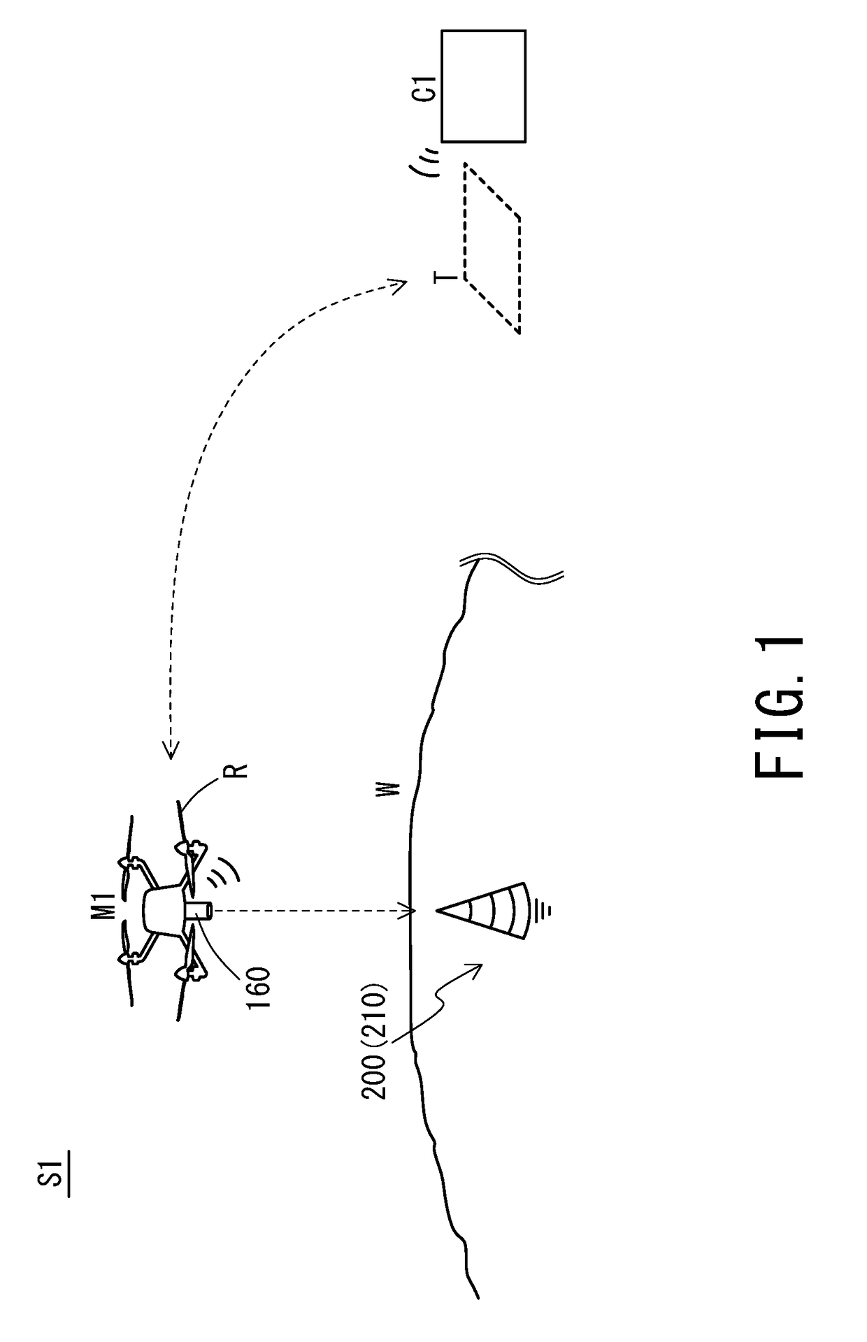
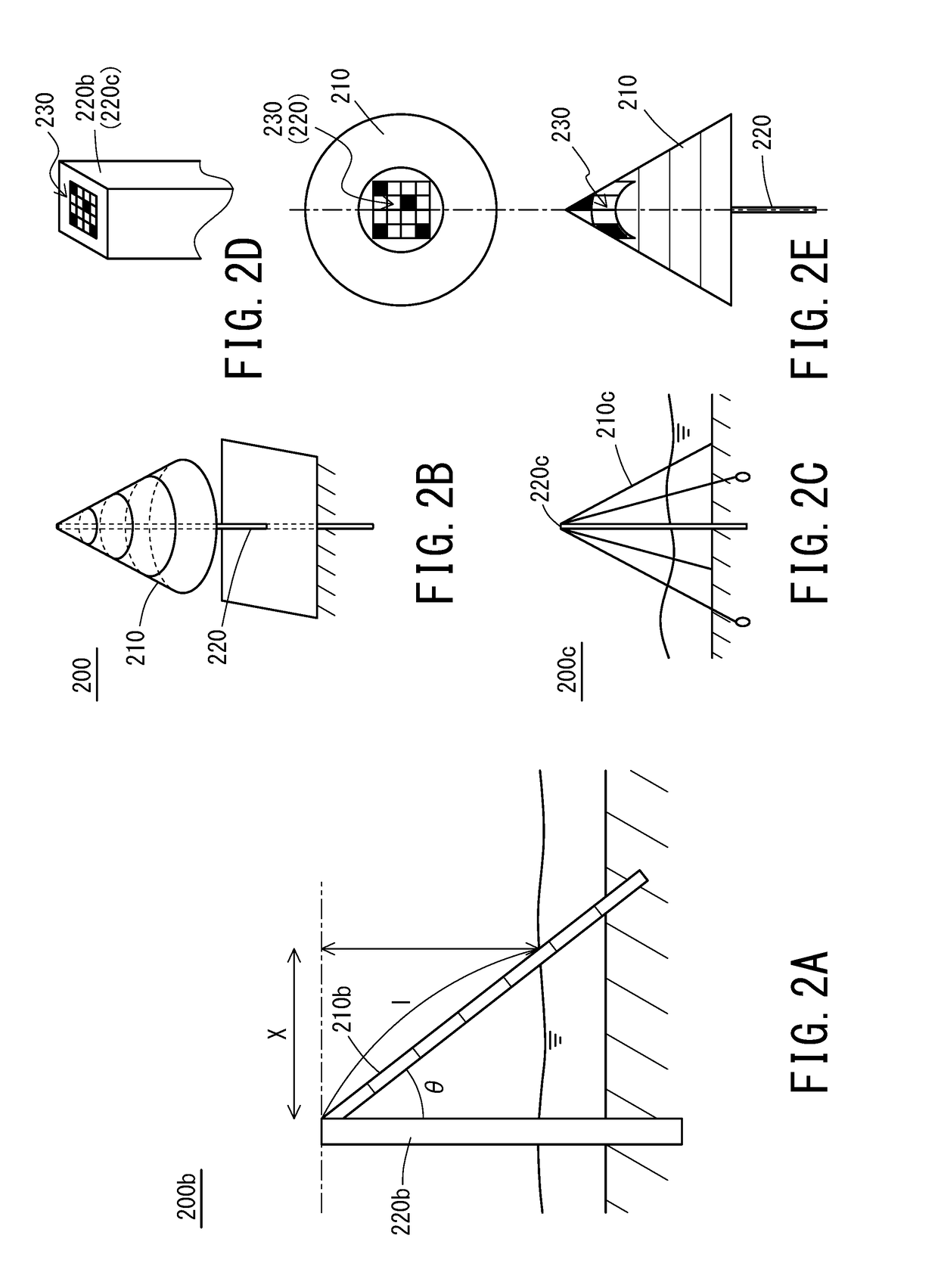
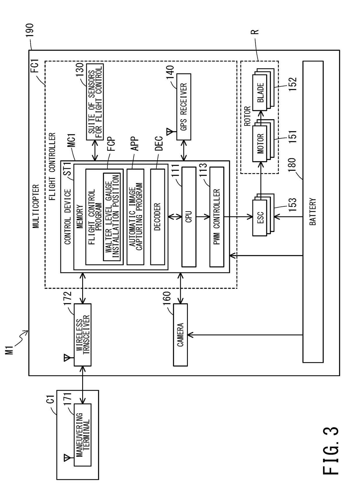
[0044]FIG. 1 is a schematic diagram depicting an aspect in which a water level measurement system S1 pertaining to a first embodiment measures the water level of the water reservoir facility W. The water level measurement system S1 is comprised mainly of a water level gauge 200 installed in the water reservoir facility W and a multicopter M1 (an unmanned aerial vehicle equipped with a plurality of rotary wings) which captures images of the water level gauge 200 from above with a camera 160 (image capturing means). An external surface of the water level gauge 200 corresponds to a scale part 210 marked with a scale indicating a water level and the scale part 210 is made to be a conic surface whose outside diameter decreases in an upward direction from a water surface.

[0045]In the water level measurement system S1, since the scale part 210 of the water level gauge 200 extends upward at an angle from the water surface, it is possible to catch sight of the sc...

second embodiment

[0064]A second embodiment of the present invention is described below with the aid of the drawings. FIG. 4 is a schematic diagram depicting an aspect in which adjustment is made of the water level of the water reservoir facility W by a water level control system S2 pertaining to the second embodiment. FIG. 5 is a block diagram depicting a functional configuration of the water level control system S2 pertaining to the second embodiment. Now, in the following description, a component having the same function as in the foregoing embodiment is assigned the same reference designator as in the foregoing embodiment and its detailed description is omitted. Also, a component having basic functions in common with the corresponding one in the foregoing embodiment is assigned the reference designator, with only a suffixed number changed, of the corresponding one in the foregoing embodiment, and a description about the basic functions is omitted.

[0065][Overall Configuration]

[0066]The water level...

third embodiment

[0082]A third embodiment of the present invention is described below with the aid of the drawings. FIG. 6 is a schematic diagram depicting an aspect in which adjustment is made of the water level of the water reservoir facility W by a water level control system S3 pertaining to the third embodiment. FIG. 7 is a block diagram depicting a functional configuration of the water level control system S3 pertaining to the third embodiment. Now, in the following description, a component having the same function as in the foregoing embodiments is assigned the same reference designator as in the foregoing embodiments and its detailed description is omitted. Also, a component having basic functions in common with the corresponding one in the foregoing embodiments is assigned the reference designator, with only a suffixed number changed, of the corresponding one in the foregoing embodiment, and a description about the basic functions is omitted.

[0083][Overall Configuration]

[0084]A principal con...


PUM


Abstract

A water level measurement system including: a water level gauge including a scale part which is installed to extend upward at a predetermined angle of inclination from a water surface; and an unmanned aerial vehicle including image capturing means for capturing the scale part from above and a plurality of rotary wings, and is also solved by a water level control system including the water level measurement system and water level adjustment equipment capable of adjusting an amount of water in a water area in which the water level gauge is installed, wherein the unmanned aerial vehicle includes the water level determining unit and water level control means for remotely operating the water level adjustment equipment through wireless communication, as well as a water level measurement method and a water level control method using the above systems.

Description

TECHNICAL FIELD[0001]The present invention relates to a water level measurement system and a water level control system using an unmanned aerial vehicle equipped with a plurality of rotary wings as well as a water level measurement method and a water level control method using such systems.BACKGROUND ART[0002]Water level measurement for rivers, irrigation canals, paddy fields, water reservoirs, etc. is, in most cases, performed as follows: install a water level marker (also called a water level post) with a scale in a place where it can be seen from up close and a person visually reads a water surface position indicated by the scale. Alternatively, measurement using a so-called float type, ultrasonic type, or pressure type water level gauge is generally performed. Such a water level gauge is usually installed near the waterfront of a water area which is a measuring object and a worker reads a value indicated by the water level gauge in a site, thus checking the water level.[0003]Now...

Claims


Application Information

Patent Timeline
IPC IPC(8): G01C13/00G01F23/04B64C39/02
CPCG01C13/008G01F23/04B64C39/024B64C2201/123G05D1/102G06T7/90G06T7/60G01F23/292G05D9/12G06T2207/10024G06T2207/10032G06T2207/30181G06T7/73Y02A90/30B64U2101/30B64U10/13B64U2201/10B64U30/20B64U2101/00
Inventor KUSUMOTO, SHINTAROSUGAKI, KIYOKAZUICHIHARA, KAZUO
Owner PRODRONE CO LTD
Why Eureka
Try Eureka