Evaporator unit for an inhaler and method for controlling an evaporator unit

a technology of evaporator unit and inhaler, which is applied in the direction of ohmic-resistance heating, electrical equipment, tobacco, etc., can solve the problems of significant overheating point, harmful decomposition products, and method disadvantages, so as to achieve the effect of optimising the energy input of heating element and reliably avoiding undesirable production of decomposition products

Active Publication Date: 2018-12-20
KÖRBER TECH GMBH
View PDF0 Cites 20 Cited by
  • Summary
  • Abstract
  • Description
  • Claims
  • Application Information

AI Technical Summary

Benefits of technology

[0012]By means of the evaporator comprising the air-permeable capillary structure, which is arranged downstream of the heating element, it is possible to achieve extremely precise temporal control of the evaporation and dosing of the heating power and of the vapour.
[0039]Advantageously, the capillary structure and / or the heating element are heated in a non-continuous, in particular cyclic and / or pulsed manner. This can optimise the energy input into the heating element and optionally into the capillary structure, and allows needs-based heating when evaporation is intended to be achieved, along with control of the heating power, and can be useful for the subsequent feeding of the liquid. It is advantageous for the temporal heating voltage profile Uhk(t) or the temporal heating voltage profiles Uh(t) for the heating element and Uhk(t) for the capillary structure to be specified such that a subsequent flow of liquid is ensured on the basis of the temperature. The heating power can thus be set on the basis of the feed rate and / or the feed requirements. The amount of subsequently fed liquid preferably corresponds to the amount of evaporated liquid. Therefore, there is only a subsequent flow in the amount that has been evaporated. Setting the temperature is conceivable in all cases. More preferably, the heating power of the heating element and / or of the capillary structure is kept at an upper temperature limit. This allows for reliable evaporation with the proviso that there is no overheating, and / or no harmful thermal decomposition of the liquid to be evaporated and / or of the vapour occurs. Optimum evaporation of the liquid that is adapted to the components thereof can be ensured using any of the specified methods, and an undesirable production of decomposition products can be reliably avoided.

Problems solved by technology

This method has serious disadvantages.
Firstly, the arrangement of the wick and heater varies depending on the manufacture.
Secondly, what are known as hot spots occur on the heater.
The specific resistance increases in said regions, which further increases the heating power, resulting overall in a significantly overheated point.
This can lead to harmful decomposition products and what is known as “dry puff”.
Thirdly, the evaporation of the low-boiling liquid components results in the build-up of high-boiling components in the liquid in close proximity to the heater.
In extreme cases, this can lead to the liquid boiling only away from this layer, and non-evaporated, high-boiling liquid being carried away from the layer close to the heater.
This leads to inadvertent, explosion-like spraying of the liquid.
Secondly, the amount of vapour and the heater temperature are directly linked, i.e. large amounts of vapour require high evaporation temperatures.
Thirdly, there can be uneven temperature regions at / in the region of the evaporator, which runs the risk of local liquid overheating and of harmful substances being produced.
Furthermore, this change in concentration leads to a gradual change in the composition of the liquid remaining in the liquid store, i.e. the amount of active ingredient released is uneven and changes from drag to drag.
The droplet size depends in this case on factors, inter alia condensation nuclei in the air and the cooling rate, which cannot be controlled or can be controlled only to a limited extent and which, during application, can lead to an increased intake of nicotine compared with conventional cigarettes, and thus to reduced satisfaction.
Furthermore, a composition gradient in the cross section of the wick can lead to spontaneous evaporation of liquid in the centre of the wick, which is difficult to control and leads to the release of large liquid droplets.
Other evaporation methods in which the heat is introduced into the liquid by heated surfaces or solid walls also result in nucleate boiling or film boiling, and thus in locally significantly non-stationary evaporation processes which run the risk of the spontaneous release of large liquid droplets and local overheating, since the supply of heat and the formation of the gas phase are in conflict with one another.
In addition, in this case a heater and a temperature sensor are mounted at separate points on said membrane, and therefore the local heater temperature cannot be directly measured.
There is thus the risk of complete evaporation at the heater resulting in a subsequent significant increase in temperature.
Therefore, the above-described disadvantages of conventional e-cigarettes cannot be unequivocally remedied thereby.
Said alloys are disadvantageous in that the specific resistance thereof increases with the temperature, and therefore poorly cooled regions exhibit increased resistance and thus require increased heating power.
This self-reinforcing process leads to significantly inhomogeneous temperature distributions, which in turn cause an increased and uncontrolled release of harmful substances.
In addition, the catalytic effect of the metals can lead to increased production of harmful substances.

Method used


Image

  • Evaporator unit for an inhaler and method for controlling an evaporator unit
  • Evaporator unit for an inhaler and method for controlling an evaporator unit
  • Evaporator unit for an inhaler and method for controlling an evaporator unit

Examples


embodiment 1

[0091]2. Evaporator unit (20) , characterised in that the capillary structure (40) consists of an electrically conductive material.

embodiment 2

[0092]3. Evaporator unit , characterised in that heating element (36) is designed to heat the airflow to a temperature above a boiling point of the liquid mixture, and / or in that the capillary structure (40) is designed to heat the liquid to a temperature below a boiling point of the liquid mixture and / or to a temperature of at least 100° C., preferably at least 150° C., more preferably at least 200° C. and even more preferably at least 250° C.

[0093]4. Evaporator unit according to any of the preceding Embodiments, characterised in that the capillary structure (40) is heatable by means of a first electrical / electronic unit (70), the first electrical / electronic unit (70) being designed to control the heating element (36).

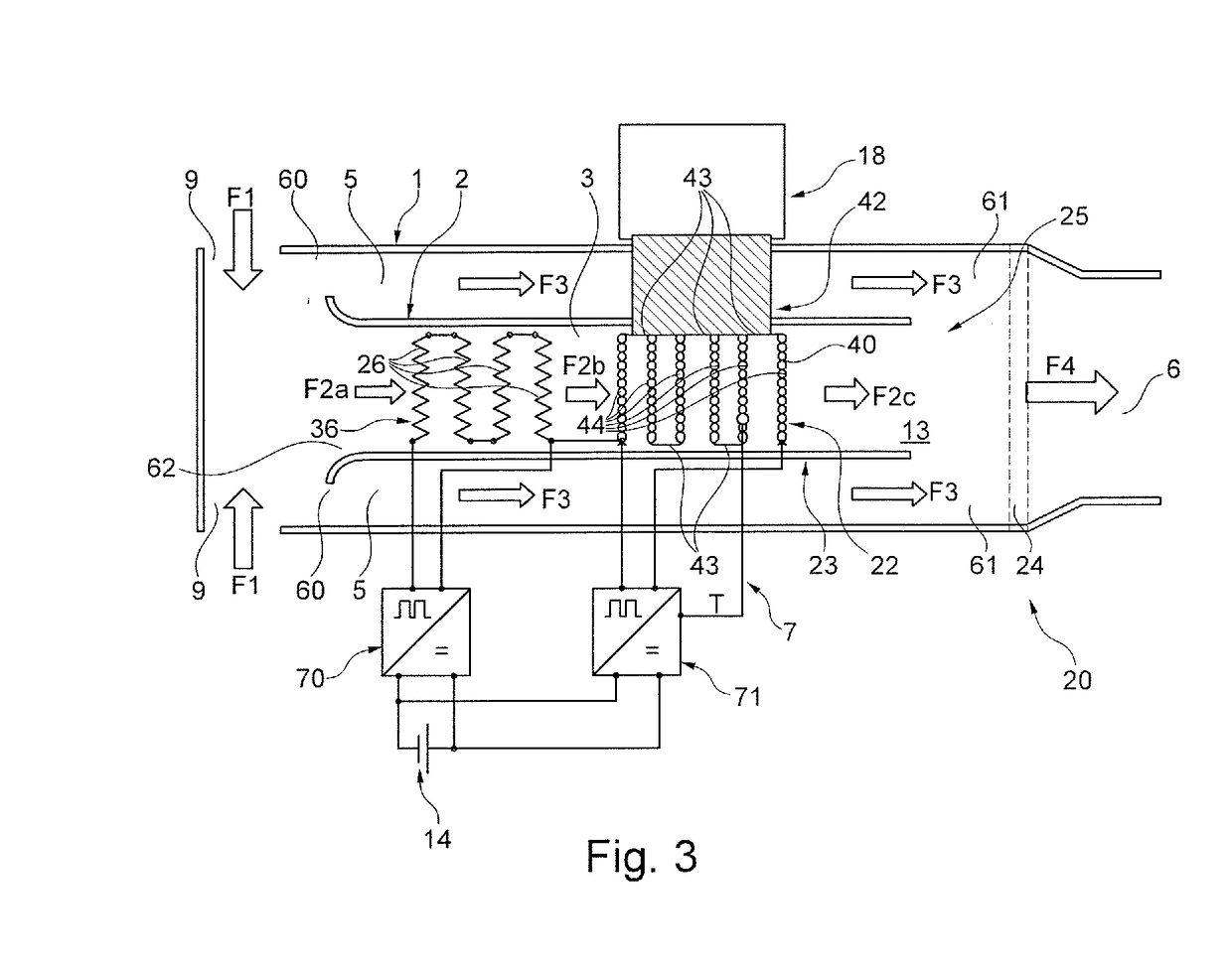
[0094]5. Evaporator unit according to any of the preceding Embodiments, characterised in that a first electrical / electronic unit (70) is designed to control the heating element (36), and the capillary structure (40) is heatable by means of a second electrical / electron...

embodiment 10

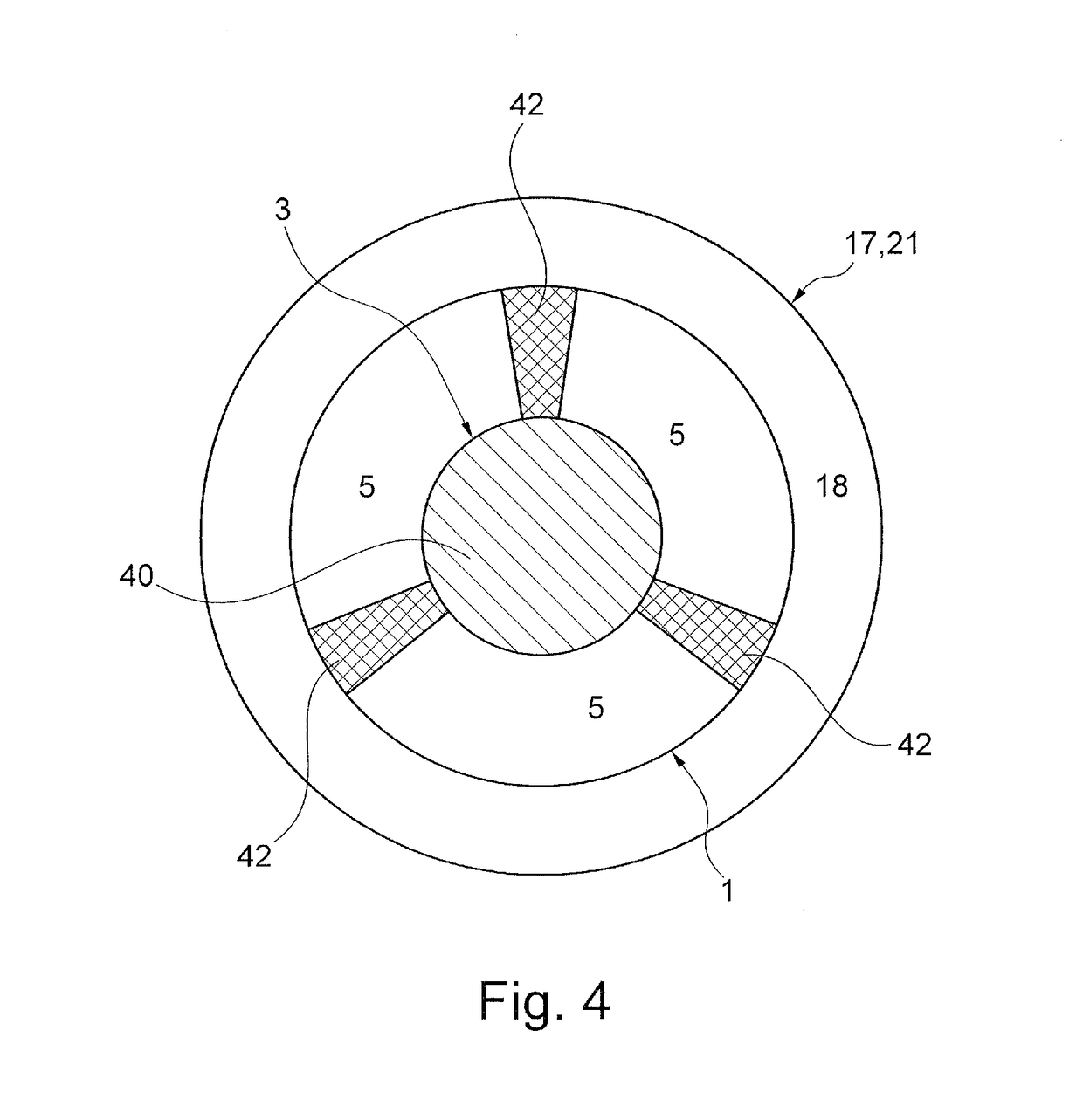
[0100]11. Evaporator unit , characterised in that the connection means (42) is designed to feed liquid by means of capillary action.


PUM


Abstract

An evaporator unit for an inhaler comprising a heating element is designed to evaporate liquid, the evaporated liquid being taken up by an airflow flowing through the evaporator unit. The evaporator unit comprises at least one air-permeable capillary structure having a surface that is heatable in order to preheat the liquid and can be wetted, at least in part, by liquid and is supplied with liquid by capillary action, and the heating element is designed to heat the airflow flowing through the evaporator unit, the capillary structure being arranged downstream of the heating element such that the heated airflow leads to evaporation of the preheated liquid.

Description

CROSS REFERENCE TO A RELATED APPLICATION[0001]This application claims priority under 35 U.S.C. § 119(e) of German Patent Application No. DE 10 2017 111 435.1, filed May 24, 2017, which is incorporated herein by reference in its entirety.FIELD OF THE INVENTION[0002]The present invention relates to an evaporator unit for an inhaler comprising a heating element, the evaporator unit being designed to evaporate liquid, the evaporated liquid being taken up by an airflow flowing through the evaporator. The invention also relates to a method for controlling an evaporator unit.BACKGROUND OF THE INVENTION[0003]Conventional e-cigarettes consist of a wick, for example made of glass fibre or cotton, and a heating wire wound around the wick or a heating grid lying on the wick or surrounding the wick. The liquid is sucked into the wick and is evaporated therein by applying a voltage to the heating wire or the heating grid. This method has serious disadvantages. Firstly, the arrangement of the wick...

Claims


Application Information

Patent Timeline
Patent Type & Authority Applications(United States)
IPC IPC(8): A24F47/00H05B1/02A24B15/16A24F40/10A24F40/44A24F40/46A24F40/485A24F40/50
CPCA24F47/008H05B1/0297A24B15/167H05B2203/021H05B2203/022A61M11/042H05B3/34H05B1/0227A24F40/46A24F40/10A24F40/44A24F40/50A24F40/485A24F40/48A24F40/42A24F40/57
Inventor SCHMIDT, RENEKESSLER, MARC
Owner KÖRBER TECH GMBH
Why Eureka
Try Eureka