Human bone treatment unit

a treatment unit and human bone technology, applied in the field of bone treatment units, can solve the problems of screw s not being screw s is damaged or broken, screw s is not easily separated from the bone, etc., to achieve smooth screw separation from the bone, increase the coupling force, and increase the reliability of treatment

Inactive Publication Date: 2018-12-20
INJE UNIV IND ACADEMIC COOP FOUND
View PDF2 Cites 0 Cited by
  • Summary
  • Abstract
  • Description
  • Claims
  • Application Information

AI Technical Summary

Benefits of technology

[0012]A human bone treatment according to the present disclosure, which has the above-described configuration as described above, includes a head part having an engagement surface provided separately from an engagement recess, and can additionally perform a screw separation operation in preparation for unexpected damage or breakage of the engagement recess. Furthermore, the human bone treatment can doubly couple the engagement recess and the engagement surface with a driver to further increase a coupling force between the screw and the driver. Thus, an advantage of enabling smooth screw separation from a bone can be expected. This advantage enables the screw separation at an appropriate time. Accordingly, goals of ultimate medical services, which can obtain treatment stability and increase reliability of treatment, can be achieved.

Problems solved by technology

However, according to this treatment method, when the screw S is fastened to the bone for a large amount of time, a coupling force between the screw S and the bone becomes large, so the screw S is not easily separated from the bone.
Since the coupling force becomes larger than a force applied to the driver to rotate the screw S, a head of the screw S is damaged or broken.
As a result, the screw S cannot be smoothly separated from the bone.
Because of this problem, the screw S may be separated from the bone while inflicting artificial damage on the bone to which the screw S is fastened, or the screw S cannot be separated from the bone at a desired time, thus frequently hindering patients' treatment stability.

Method used


Image

  • Human bone treatment unit
  • Human bone treatment unit
  • Human bone treatment unit

Examples


Embodiment Construction

Technical Problem

[0005]Accordingly, the present disclosure has been devised to solve the above-described problems. It is an object of the present disclosure to provide a human bone treatment unit capable of smoothly performing the fastening and separation of a screw that is fastened to a bone for treatment.

[0006]It is another object of the present disclosure to provide a human bone treatment unit capable of additionally attempting to separate a screw from a bone when a screw separation operation becomes impossible due to unexpected damage or breakage of the screw.

Solution to Problem

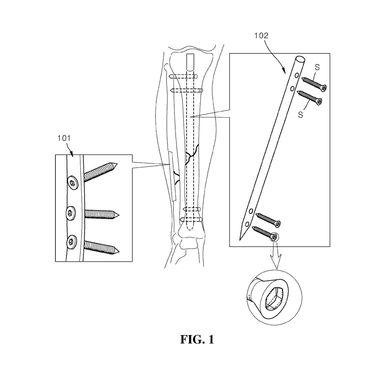
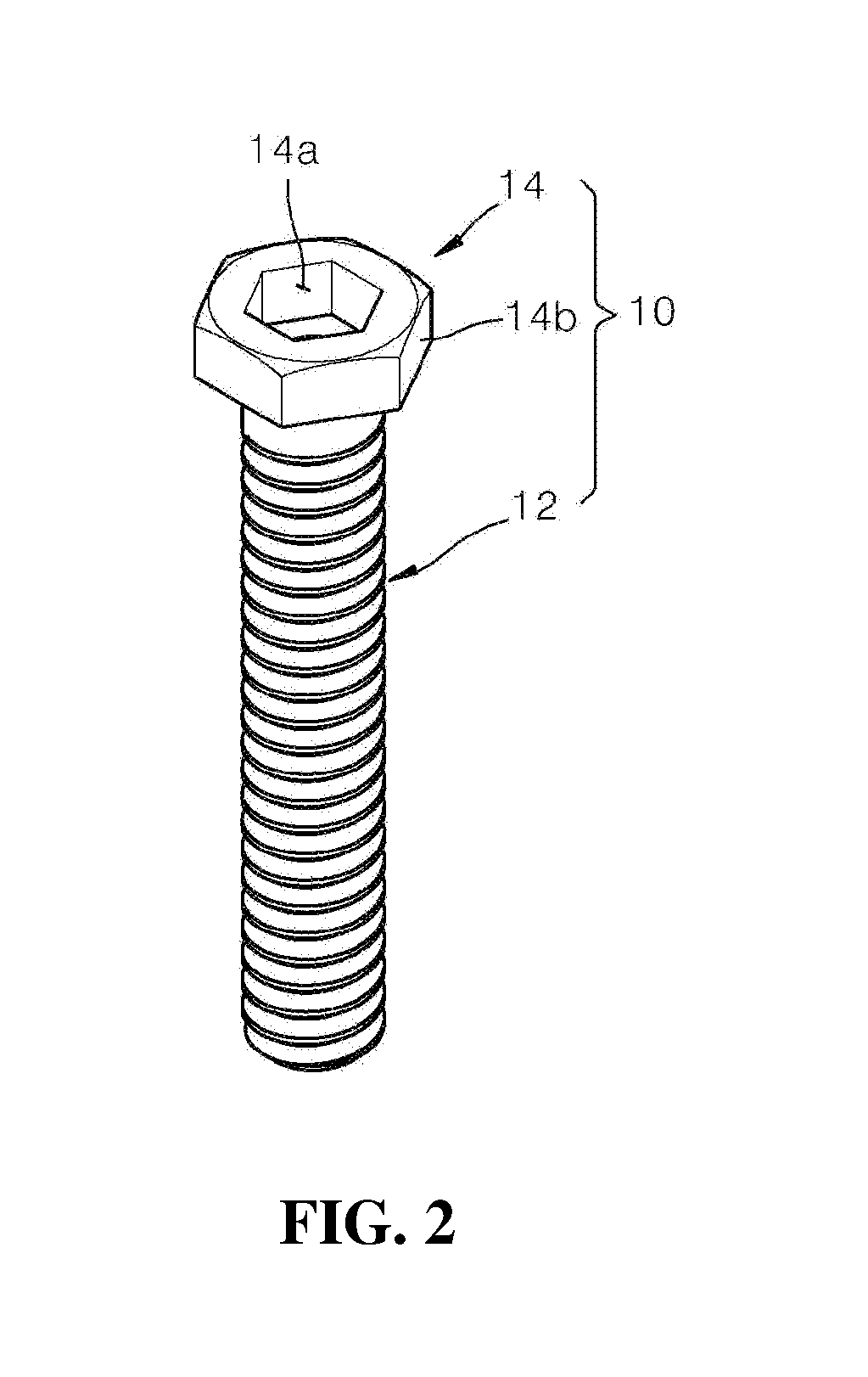
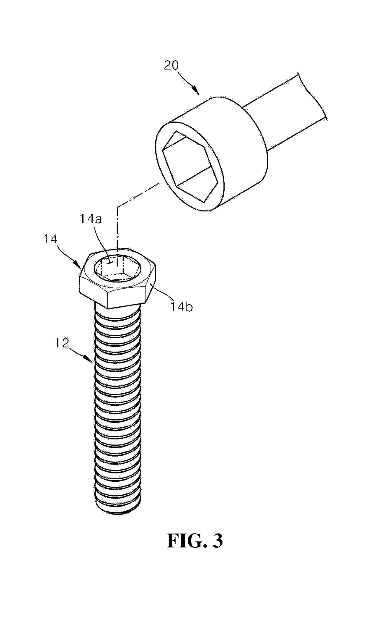
[0007]According to an aspect of the present disclosure, a human bone treatment unit, which is used to treat human bones, includes: a main body part configured to pass through a human bone and a treatment rod and then fastened to the bone; and a head part configured to enable coupling between the bone and the treatment rod by means of an external force applied from the outside, wherein the head part is int...


PUM


Abstract

Provided is a human bone treatment unit. The human bone treatment unit is used to treat human bones, and includes: a main body part that passes through a human bone and a treatment rod and is then fastened to the bone; and a head part for enabling coupling between the bone and the treatment rod by means of an external force applied from the outside, wherein the head part is integrally formed with the main body part, provided with an engagement recess having a non-circular cross-section which is engaged with a screwdriver for creating the external force, and has an engagement surface having a non-circular cross-section that makes it possible to be additionally engaged with the screwdriver in a state in which the engagement between the screwdriver and the engagement recess is not possible.

Description

TECHNICAL FIELD[0001]The present disclosure relates to a bone treatment unit used to treat human bones, and more particularly, a human bone treatment having an improved structure for facilitating the fastening and separation of a screw configured to couple a bone to be treated with a treatment rod, thereby enhancing treatment stability.BACKGROUND ART[0002]In general, in order to treat a fractured bone, as shown in FIG. 1, a process of placing a treatment rod, such as a bone plate 101 or an intramedullary (IM) rod 102, at a fracture site and coupling the treatment rod and the bone with each other using a screw S has been performed.[0003]However, according to this treatment method, when the screw S is fastened to the bone for a large amount of time, a coupling force between the screw S and the bone becomes large, so the screw S is not easily separated from the bone. Since the coupling force becomes larger than a force applied to the driver to rotate the screw S, a head of the screw S ...

Claims


Application Information

Patent Timeline
Patent Type & Authority Applications(United States)
IPC IPC(8): A61B17/86
CPCA61B17/8615A61B17/862A61B17/8625A61B17/8888A61B17/72A61B17/864A61B17/888A61B17/8883A61B17/8057A61B17/808A61B17/8894
Inventor KWON, YOUN UKKONG, GYU MIN
Owner INJE UNIV IND ACADEMIC COOP FOUND
Why Eureka
Try Eureka