Variable Resolution Light Radar System

a radar system and variable resolution technology, applied in the field of measurement systems, can solve the problems of low resolution of the target region, limited pulse rate and power, and only one resolution of the lidar system throughout the entire scan

Active Publication Date: 2018-12-20
THE BOEING CO
View PDF0 Cites 11 Cited by
  • Summary
  • Abstract
  • Description
  • Claims
  • Application Information

AI Technical Summary

Problems solved by technology

These types of lidar systems, however, provide only one resolution throughout the entire scan.
The target region, however, may be limited by the pulse rate and power of the lidar system.
Increasing the size of the target region may result in a lower resolution.
As a result, having a desired size for a target region may not be possible with a desired resolution.

Method used


Image

  • Variable Resolution Light Radar System
  • Variable Resolution Light Radar System
  • Variable Resolution Light Radar System

Examples


Embodiment Construction

[0027]The illustrative embodiments recognize and take into account one or more different considerations. For example, the illustrative embodiments recognize and take into account that in some applications, different resolutions may be desired for different portions of a target region that is being scanned.

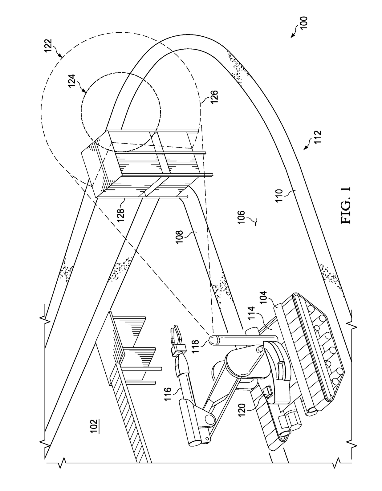
[0028]For example, when navigating an autonomous mobile platform such as a robot, a high resolution is desired on the path in the direction of travel for the robot while a low resolution is appropriate for the periphery around the path. As a result, one lidar system may be used with a high resolution while a second lidar system may be used with a low resolution.

[0029]The illustrative embodiments recognize and take into account that the resolution requires more than one lidar system and may use more power, have a greater cost, and more complexity than a single lidar system. For example, the illustrative embodiments recognize and take into account that with an autonomous mobile robot...


PUM


Abstract

A method and apparatus for scanning a target region. A divergence of a laser beam during scanning of the target region is set. The laser beam is directed to different locations in the target region at a scan angle. The scan angle of the laser beam is set while the laser beam is directed to the different locations. Changing at least one of the divergence or an amount of change in the scan angle during scanning of the target region changes a resolution for the target region.

Description

BACKGROUND INFORMATION1. Field[0001]The present disclosure relates generally to measurement systems, and in particular, to measurement systems that use light. Still more particularly, the present disclosure relates to a method and apparatus for radar systems generating measurement information using light radar (lidar) systems.2. Background[0002]Lidar is a sensing technology that measures distance by illuminating a target with a laser and analyzing responses to the illumination of the target. The word “lidar” is portmanteau of the words “laser” and “radar”, rather than an acronym.[0003]Lidar systems are used for many different applications. For example, lidar systems may be used in seismology, point cloud generation, mapping, contour mapping, image generation, navigation, and other applications.[0004]With respect to navigation, a lidar system may be used for obstacle detection and avoidance when navigating a mobile platform through an environment. For example, a point cloud of the en...

Claims


Application Information

Patent Timeline
Patent Type & Authority Applications(United States)
IPC IPC(8): G01S7/481G01S17/89G01B11/26G01S17/931
CPCG01S7/4817G01S17/89G01B11/26G01S17/936G01S17/10G01S7/4814G01S17/42G01S7/497G02B7/021G02B7/10G02B26/101G01S17/931G02B26/10
Inventor JUNGWIRTH, DOUGLAS R.BOUCKAERT, ANTON M.
Owner THE BOEING CO
Why Eureka
Try Eureka