
Semiconductor device and power conversion circuit

a technology of power conversion circuit and semiconductor device, which is applied in the direction of semiconductor device, semiconductor/solid-state device details, electrical apparatus, etc., can solve the problems of low power conversion efficiency, huge power consumption, and difficulty in significantly reducing connection resistance, so as to achieve the effect of effectively enhancing power conversion efficiency

Inactive Publication Date: 2018-12-20
UPI SEMICON CORP
View PDF2 Cites 0 Cited by
  • Summary
  • Abstract
  • Description
  • Claims
  • Application Information

AI Technical Summary

Benefits of technology

The patent text describes a new design for semiconductor devices, specifically focused on improving power conversion efficiency. By arranging certain parts of the semiconductor device in a specific way, the connection resistance and diffusion resistance can be reduced, resulting in better performance and lower power consumption. Additionally, the arrangement of certain parts can also reduce noise and prevent accidental displacement of the device during packaging. Overall, this design allows for faster switching, higher power conversion efficiency, and better stability of the semiconductor device during power conversion.

Problems solved by technology

However, in the MOSFET described in the above-mentioned prior arts, since the gate electrode, the source electrode and the drain electrode of the MOSFET have substantially the same size, it is difficult to significantly reduce the connection resistance.
However, this will increase unnecessary inductance on the conductive path of the package substrate side and impede high-speed switching, resulting in huge power consumption and low power conversion efficiency.
In addition, if the areas of the gate electrode, the source electrode and the drain electrode are increased, the amount of solder used in the packaging process will increase, and it will become difficult to stably package the semiconductor device.

Method used


Image

  • Semiconductor device and power conversion circuit
  • Semiconductor device and power conversion circuit
  • Semiconductor device and power conversion circuit

Examples


Embodiment Construction

[0042]Exemplary embodiments of the semiconductor device 10 in the present invention are referenced in detail now, and examples of the exemplary embodiments are illustrated in the drawings. Further, the same or similar reference numerals of the elements / components in the drawings and the detailed description of the invention are used on behalf of the same or similar parts.

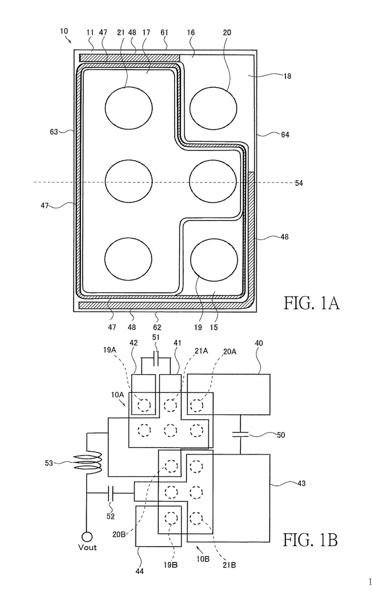
[0043]Please refer to FIG. 1A and FIG. 1B. FIG. 1A is a plan view of the semiconductor device 10 and FIG. 1B is a plan view of the semiconductor device 10 packaged on the conductive path of the package substrate 11.

[0044]As shown in FIG. 1A, the semiconductor device 10 is a metal-oxide-semiconductor field-effect transistor (MOSFET), and the MOSFET has a gate region, a source region and a drain region formed in the semiconductor substrate 11. Specifically, the semiconductor device 10 includes the semiconductor substrate 11, and the gate electrode 15, the drain electrode 16 and the source electrode 17 are formed on th...


PUM


Abstract

A semiconductor device is disclosed. The semiconductor device includes a semiconductor substrate, a gate electrode, a drain electrode and a source electrode. The gate electrode, the drain electrode and the source electrode are formed on the semiconductor substrate. An area of the source electrode is larger than an area of the gate electrode and the area of the drain electrode. A part of the source electrode has a convex shape and disposed between the gate electrode and the drain electrode. The semiconductor device of the invention can maintain various switching characteristics and enable high-speed switching.

Description

BACKGROUND OF THE INVENTION1. Field of the Invention[0001]The invention relates to a semiconductor device; in particular, to a semiconductor device and a power conversion circuit having a gate electrode, a source electrode and a drain electrode.2. Description of the Prior Art[0002]With the trend toward miniaturization and thinning of mobile electronic devices, package substrates and power conversion semiconductor devices built into the mobile electronic devices (e.g., smart phones or tablet computers) are bound to be miniaturized and thinned.[0003]The prior art is a lead frame type package in which a lead exposed is used from the side of the sealing resin sealing the semiconductor element to the other side. However, when the lead frame type package is mounted on a package substrate using a solder, since solder is formed on a side of the lead frame type package, the lead frame type package needs a large packaging area, thereby miniaturization and thinning of package substrates and mo...

Claims


Application Information

Patent Timeline
Patent Type & Authority Applications(United States)
IPC IPC(8): H01L29/78H01L29/417H01L29/06H01L23/64
CPCH01L29/7813H01L29/41741H01L29/0653H01L23/645H01L23/647H01L29/41775H01L29/42356H01L23/49844H01L23/64H01L25/072H01L29/7809H01L29/41766H01L29/1095H01L29/4238H01L2224/0603
Inventor SHIRAI, NOBUYUKIMATSUURA, NOBUYOSHI
Owner UPI SEMICON CORP
Learn More