Draper Head with Multipart Screw Conveyor

a screw conveyor and screw head technology, applied in the field of cutting system, can solve the problems of disadvantages of screw conveyor, and achieve the effects of reducing the number of screw conveyors, and improving the efficiency of screw conveyors

Inactive Publication Date: 2018-12-27
CARL GERINGHOFF GMBH & CO KG
View PDF16 Cites 5 Cited by
  • Summary
  • Abstract
  • Description
  • Claims
  • Application Information

AI Technical Summary

Benefits of technology

[0016]According to one embodiment of the invention, the screw conveyor segments are attached to their respective frame part or to the respective rear wall. In particular when the supporting elements that support the cutter bar and/or the guide and drive elements of the belt conveyor systems are movable relative to the frame and/or the rear wall, attachment of the screw conveyor segment to the frame or to the rear wall prevents the screw conveyor segment from participating in the movements of such supporting elements. As a result, the drive of the screw conveyor can be simplified, and the function is more reliable, independently of the swinging of the supporting elements and of the frame parts with respect to each other.
[0017]According to one embodiment of the invention, the spiral sheets on one section of the central screw conveyor segment feature a stronger gradient than spiral sheets on a section of the lateral screw conveyor segment. The stronger gradient of the spiral sheets on the central screw conveyor segment effectuates a faster discharge of the harvested crop transported by the screw conveyor. The faster discharge improves the reception of the harvested crop transported by the lateral screw conveyor segments to the central screw conveyor segment.
[0018]According to one embodiment of the invention, a cone covering the universal joints is positioned on the screw conveyor in the area of the universal joints. The cone improves the material flow in the area of the transition from the lateral screw conveyor segment to the central screw conveyor segment. Due to the cone form that widens in the directio

Problems solved by technology

There, however, such a screw convey

Method used


Image

  • Draper Head with Multipart Screw Conveyor
  • Draper Head with Multipart Screw Conveyor
  • Draper Head with Multipart Screw Conveyor

Examples


Embodiment Construction

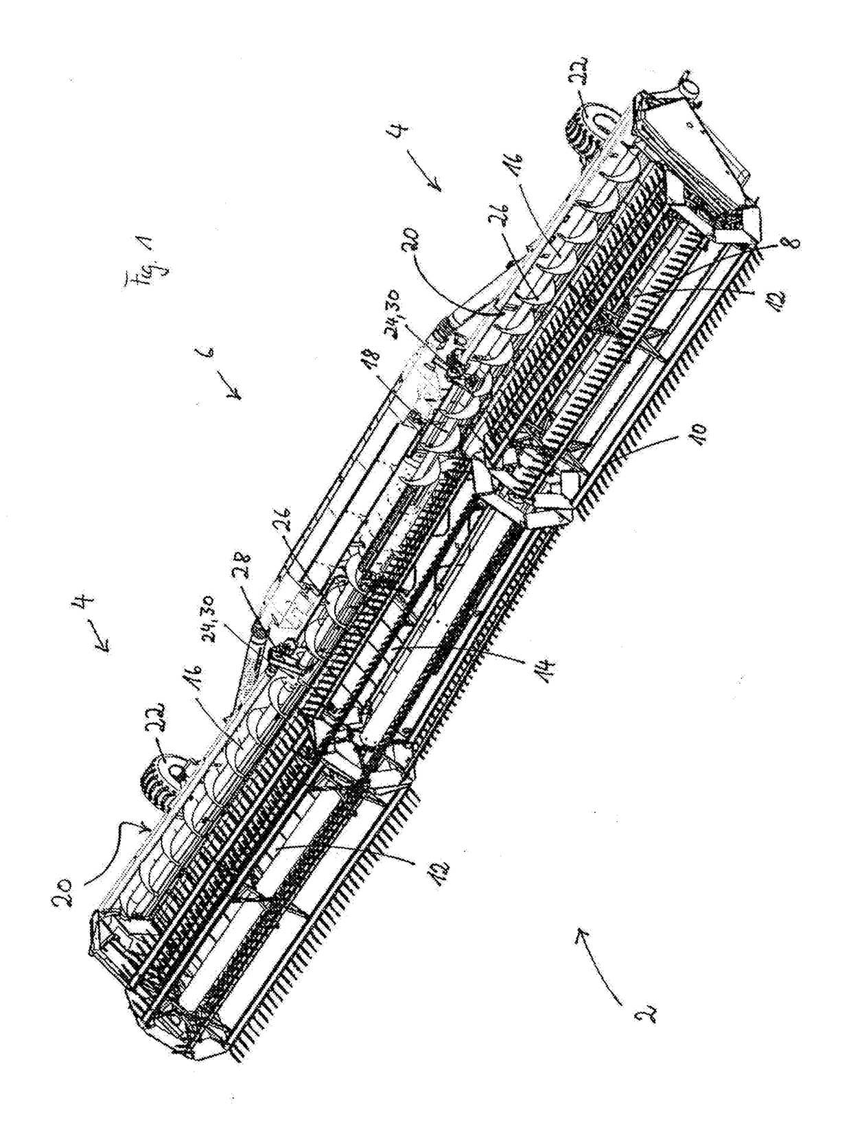
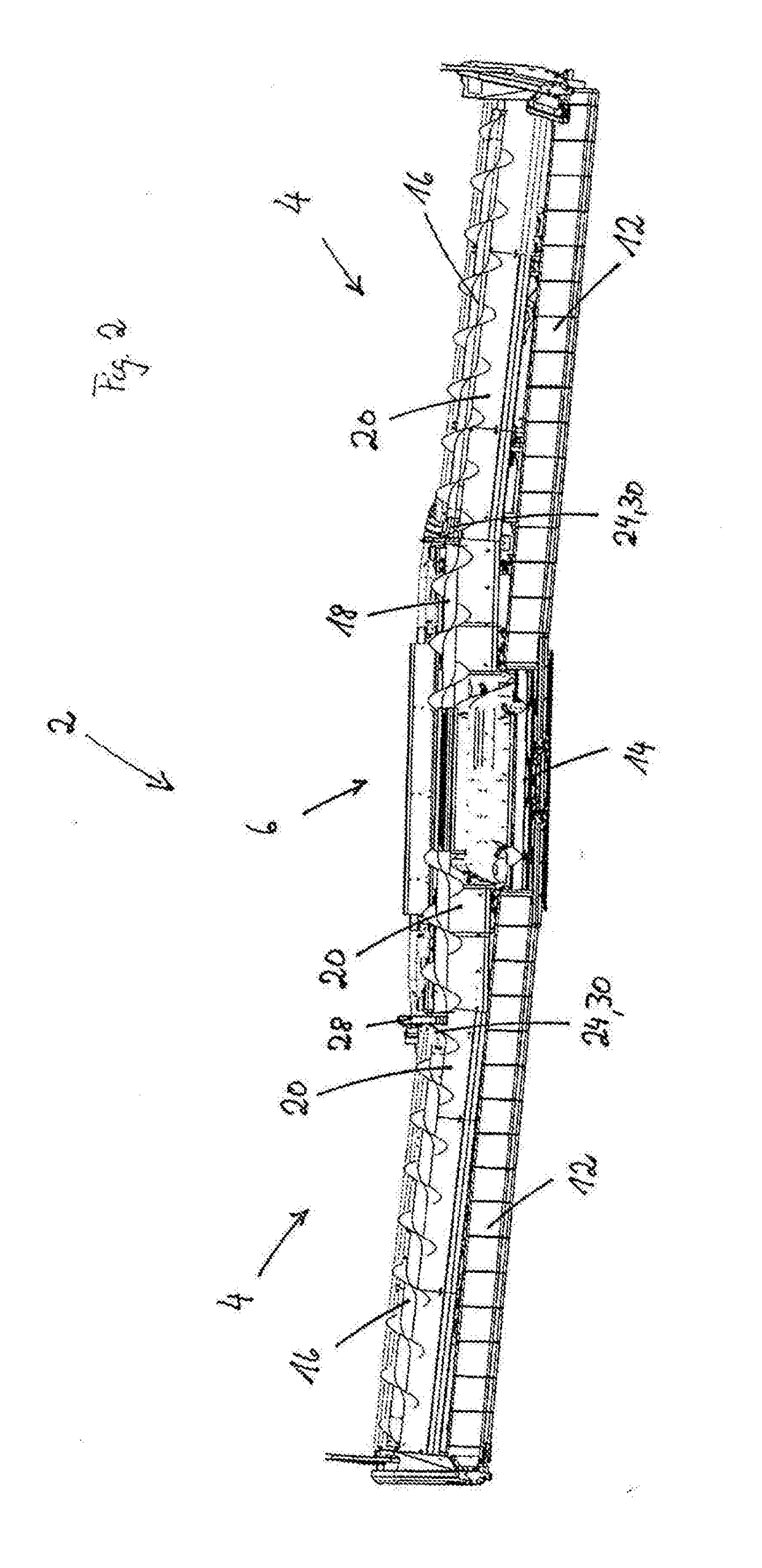
[0031]FIG. 1 shows an oblique top view of a cutting system 2. The cutting system 2 features a three-part frame consisting of two lateral frame parts 4 and a central frame part 6. At the front of the cutting system 2 when viewed in the travel direction, there is a cutter bar 10. The three-part reel 8 [shown] in the exemplary embodiment is located above the cutter bar 10. The harvested crop cut by the cutter bar 10 is discharged by the reel 8 onto the two lateral belt conveyor systems 12 and the central belt conveyor system 14. The two lateral belt conveyor systems 12 transport the harvested crop transversely to the direction of travel onto the central belt conveyor system 14, which discharges the harvested crop backward, in the direction contrary to the direction of travel, onto the slope conveyor of a combine harvester that is connected to the cutting system.

[0032]A rear wall 20 is located in the rear area of the cutting system 2, constructed on the respective frame parts 4, 6 and e...


PUM


Abstract

A cutting system for a combine harvester has a three-part frame with frame parts articulately joined with each other. A cutter bar, a reel, a central belt conveyor system, and lateral belt conveyor systems for discharging the cut stalk material are supported by the frame. The lateral belt conveyor systems move transversely to the travel direction towards the central belt conveyor system. The central belt conveyor system moves contrary to the travel direction. To prevent accumulation of crop material near the rear wall of the lateral belt conveyor systems, a three-part screw conveyor is arranged near the rear wall and extends across the operating width of the cutting system such that the length of the screw conveyor parts corresponds at least approximately to the width of the frame parts. The screw conveyor parts are powered by a joint drive. Adjacent screw conveyor parts are mutually connected by universal joints.

Description

BACKGROUND OF THE INVENTION[0001]The present invention relates to a cutting system for being attached to a combine harvester with a three-part frame, the frame parts of which are articulately joined with each other, a cutter bar, a reel, a central belt conveyor system as well as lateral belt conveyor systems for disposing of the cut stalk material that are supported on the frame, such that the lateral belt conveyor systems convey transversely to the direction of travel in the direction of the central belt conveyor system, and the central belt conveyor system conveys contrary to the direction of travel, a multi-part rear wall of the cutting system embodied on the frame parts, which extends along the conveyor line of the lateral belt conveyor system and which features a discharge opening for discharging the harvested crop to the combine harvester in the area of the central belt conveyor system, and drive units in order to drive the cutter bar and the belt conveyor systems.[0002]In DE ...

Claims


Application Information

Patent Timeline
IPC IPC(8): A01D41/14A01D69/00A01D57/20A01D34/835
CPCA01D41/142A01D69/00A01D57/20A01D34/8355A01D61/002A01D61/004
Inventor SCHULZE SELTING, STEPHANSUDHUES, STEFFENSCHULZE RUCKAMP, JANHARTMANN, CHRISTOPHWEBERMANN, DIRKBRINKMANN, MARTIN
Owner CARL GERINGHOFF GMBH & CO KG
Why Eureka
Try Eureka